
Abstract: This article establishes a prediction model for gear honing force in CNC internal gear power honing. Firstly, the mathematical models of the contact line and cutting thickness during the engagement process of gear honing are derived, and based on this model, the grinding edge of gear honing wheel is discretized into micro-grinding edges. Then, a micro-grinding edge model of the honing wheel is constructed based on the plane grinding model, and a prediction model for gear honing force in gear honing is established. The variation rule of the honing force with process parameters is also analyzed. Finally, gear honing force measurement experiments are conducted using the Fassler HMX-400 CNC internal gear power honing machine and its built-in Kistler force sensor. The experimental results show that the predicted values of gear honing force are consistent with the experimental measurements in terms of both numerical value and trend, indicating the effectiveness of the proposed honing force prediction method.
1. Introduction
Internal gear power honing is a common precision machining process for gears, which can achieve high tooth surface quality and residual stress after processing. However, there is currently limited research on directly modeling gear honing force through mathematical methods. Most studies model the honing force through experiments or simulations, with little research on the formation mechanism of gear honing force. Starting from the machining mechanism of gear honing and combining the engagement process of gear honing, this paper establishes a mathematical model of gear honing force to predict gear honing force under different process parameters.
2. Modeling of Contact Line and Cutting Thickness in Internal Gear Honing
2.1 Principle of Internal Gear Power Honing
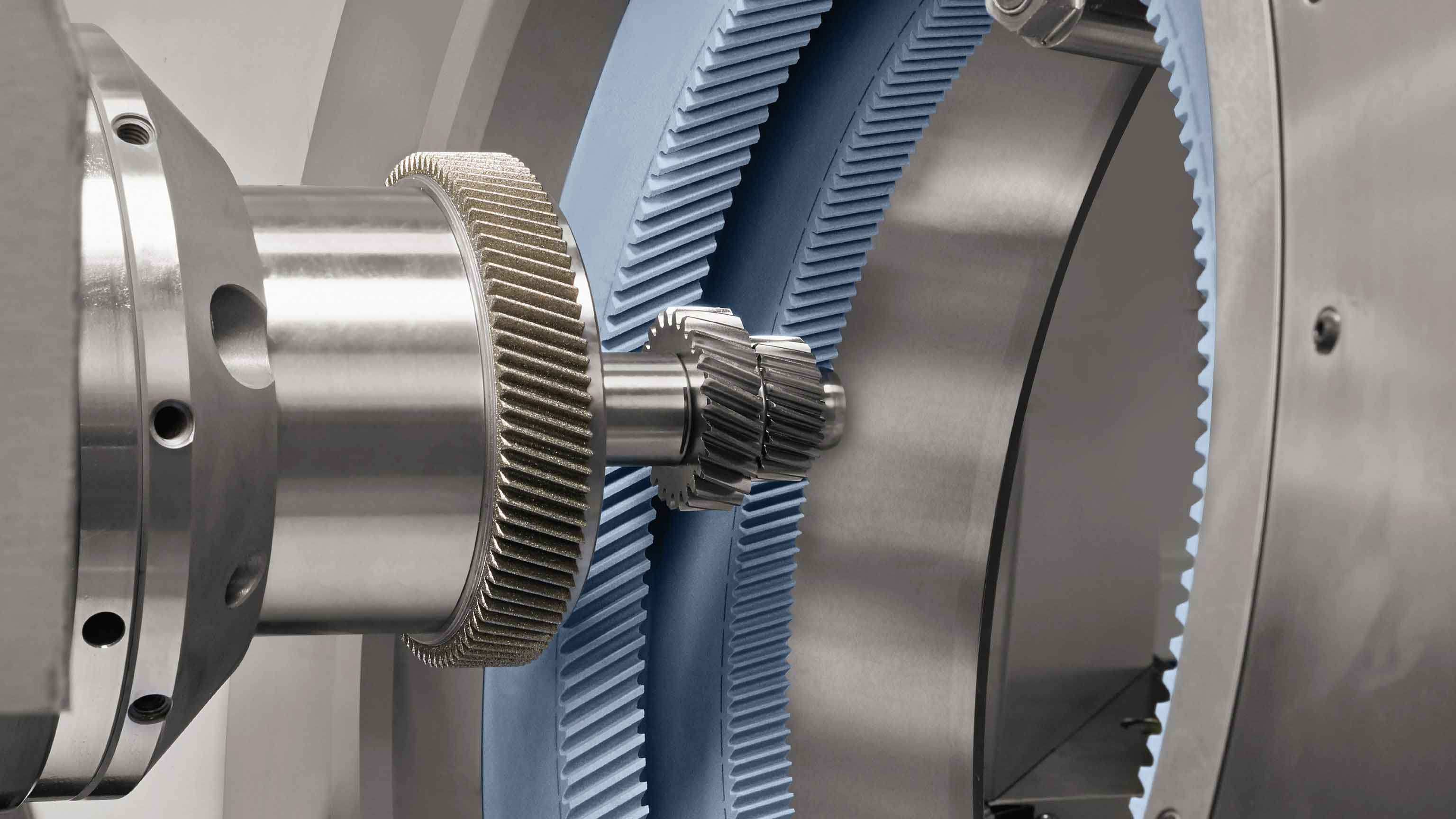
Internal gear power honing is a precision machining process in which the workpiece and the internal honing wheel engage with a determined transmission ratio. The process is similar to the meshing motion of crossed-axis helical gears,. During the forced engagement, the metal on the workpiece surface is squeezed and slipped against the abrasive grains on the surface of the internal honing wheel, removing an extremely thin layer of metal, and the entire tooth surface is machined through radial and axial feeds. The main movements of the machine tool during processing include the forced engagement motion between the workpiece gear shaft C1 and the honing wheel shaft C2, radial feed motion, and reciprocating motion of gear honing wheel along the axial direction.
2.2 Mathematical Model of Tooth Surface Contact Line
To establish gear honing force prediction model, it is necessary to first analyze the engagement process of the honing force. Firstly, a honing contact line model is established, and a spatial coordinate system for honing is established based on the positional relationship between the honing wheel and the workpiece during the honing process,.
According to the gear meshing principle, during the conjugate contact process of two tooth surfaces, the component of the relative sliding velocity at the meshing contact point in the direction of the common normal to the two surfaces is zero. Therefore, the condition that should be satisfied at the meshing point between the tooth surface of the internal honing wheel and the workpiece tooth surface is: v12 × n = 0, where v12 is the relative motion velocity at any contact point between the workpiece tooth surface and the internal honing wheel, and n is the normal vector at the contact point on the workpiece tooth surface.
2.3 Modeling of Cutting Thickness
The actual cutting thickness f1′ at the contact point C can be expressed as: f1′ = f1 * EH / (EH + EW), where EH and EW are the elastic moduli of the workpiece and honing wheel, respectively.
3. Prediction Model of Honing Force
3.1 Plane Grinding Force Model
The gear honing process essentially involves the grinding process between the abrasive grains on the honing wheel and the workpiece. Therefore, before establishing gear honing force prediction model, a grinding force model needs to be established first. Most of the grinding force models proposed by previous scholars ignore the effects of plowing and variable friction coefficients, assuming that the influence of plowing is very small compared to the chip formation force. However, in the honing process, the feed rate is small, so the influence of plowing force must be considered. This paper adopts the Werner grinding force model established in literature [11] and establishes a new grinding force model based on this model.
3.2 Derivation of Honing Force Prediction Model
By discretizing the engagement area during gear honing process and discretizing gear honing wheel into micro-grinding edges, the grinding force on each micro-grinding edge is projected and accumulated onto gear honing wheel to establish gear honing force prediction model. The unit length grinding force on the micro-grinding edge can be calculated using the formula derived earlier. By decomposing and summing the grinding forces on each micro-element along the contact line according to the formula, the honing force generated on that contact line can be obtained. By summing the grinding forces of the m micro-grinding edges participating in the grinding, the vector of the honing force experienced by the entire honing wheel in the fixed coordinate system of the workpiece can be obtained.
4. Simulation and Experimental Analysis
4.1 Simulation and Experimental Parameters
To verify the validity of the established honing force model, relevant numerical calculations and honing experiments were conducted. The geometric parameters and cutting parameters of gear honing wheel and workpiece gear used in the numerical calculations and experiments are listed in Table 1.
| Parameter | Value (Workpiece Gear) | Value (Honing Wheel) |
|---|---|---|
| Number of teeth (z1) | 123 | – |
| Module (m1, m2) | 2.25 | 2.25 |
| Helix angle (αn1, αn2) / (°) | 17.5 | 17.5 |
| Tilt angle (β1, β2) / (°) | 33 | 41.72 |
| Face width (b1, b2) / mm | 27 | 30 |
| Elastic modulus (EW, EH) / GPa | 207 | 70 |
4.2 Experimental Design for Honing Force Measurement
The Fassler HMX-400 CNC internal gear power honing machine produced by Swiss Daetwyler was used for the honing force measurement experiments. The force measurement device was the built-in Kistler force sensor of gear honing machine, and no additional sensor was required. The radial force (i.e., the x-direction honing force) during gear honing process could be directly read from the machine panel. The main technical performance parameters and processing range of the Fassler HMX-400 are listed in Table 2.
| Technical Performance | Values |
|---|---|
| Honing wheel diameter | Various sizes available |
| Workpiece diameter | Various sizes available |
| Feed rate | 20, 30, 40, 50, 60, 80 mm/min |
| Workpiece spindle speed | 800–1800 r/min |
4.3 Result Analysis
The analysis and experiments were conducted according to the above-mentioned honing force prediction model and experimental scheme. In the gear honing process, the spindle speed n2 and the radial feed rate fx of gear honing wheel are the main process parameters that affect gear honing force. The axial reciprocating speed of the honing wheel remained constant at 60 mm/min. For ease of analysis, the mean square value of the radial honing force over one cycle during the gear honing process was taken as the analysis object, and the predicted values of gear honing force model were compared with the experimental values.