
Gears serve as critical transmission components across industries, where demands for precision, strength, and noise reduction continuously escalate. Internal gear power honing emerges as a pivotal finishing technique, enhancing surface quality, compressive residual stress, and generating unique chevron textures that dampen acoustic emissions. However, fluctuations in honing forces during gear honing compromise process robustness, triggering self-excited vibrations and regenerative effects that degrade quality. Establishing an accurate predictive model for honing forces becomes essential for optimizing stability, avoiding chatter, and refining cutting parameters.
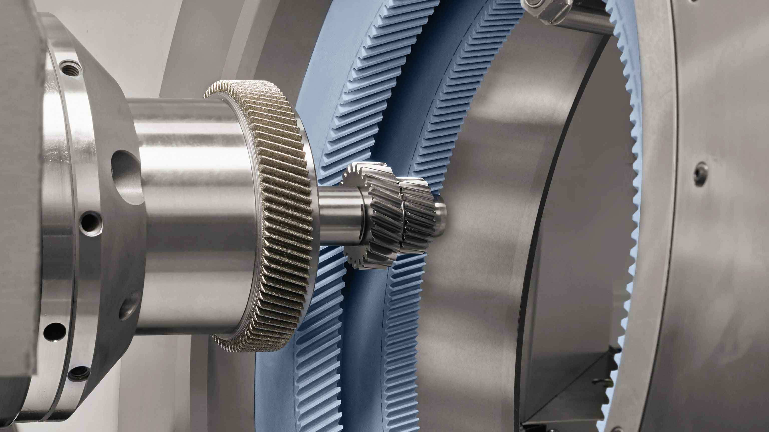
Internal gear power honing resembles crossed-helical gear meshing. The workpiece rotates synchronously with the honing wheel under enforced transmission ratios, while radial feed (\(f_x\)) and axial reciprocation complete material removal. Key motions include workpiece rotation (\(C_1\)), honing wheel rotation (\(C_2\)), radial infeed, and axial oscillation. The shaft angle \(\Sigma\) is calculated as:
$$\Sigma = \beta_2 – \beta_1$$
where \(\beta_1\) and \(\beta_2\) denote the helix angles of the workpiece and honing wheel, respectively.
Mathematical Modeling of Contact Line and Cutting Thickness
The tooth surface adheres to a standard involute helicoid. Within the workpiece coordinate system (\(O_1-x_1y_1z_1\)), the surface equation is:
$$x_1 = r_{b1}\cos(\sigma_0 + \theta + \lambda) + r_{b1}\lambda\sin(\sigma_0 + \theta + \lambda)$$
$$y_1 = r_{b1}\sin(\sigma_0 + \theta + \lambda) – r_{b1}\lambda\cos(\sigma_0 + \theta + \lambda)$$
$$z_1 = \theta p$$
where \(r_{b1}\) is base radius, \(\sigma_0\) is the starting angle, \(\lambda\) is the involute development angle, \(\theta\) is the rotation angle, and \(p\) is the helical parameter.
Conjugate contact requires the relative velocity (\(v_{12}\)) and normal vector (\(\mathbf{n}\)) to satisfy:
$$\mathbf{v}_{12} \cdot \mathbf{n} = 0$$
The relative velocity in the fixed coordinate system (\(O_g-x_gy_gz_g\)) is:
$$\mathbf{v}_{12} = \omega_1 \begin{bmatrix} -y + (y\cos\Sigma + z\sin\Sigma)/i_{12} \\ x – (x + a)\cos\Sigma / i_{12} \\ -(x + a)\sin\Sigma / i_{12} \end{bmatrix}$$
Combining with the normal vector derived from the surface gradient yields the meshing condition:
$$(a p \cos\Sigma – r_{b1}^2 \sin\Sigma) \cos(\sigma_0 + \theta + \lambda + \phi_1) + (\theta p^2 – \lambda r_{b1}^2) \sin\Sigma \sin(\sigma_0 + \theta + \lambda + \phi_1) + (p \cos\Sigma – a \sin\Sigma – i_{12}p) r_{b1} = 0$$
Solutions for \(\theta\), \(\lambda\), and \(\phi_1\) define contact lines. For multiple simultaneous meshing pairs (overlap ratio >2), contact lines phase-shift by the angular pitch \(\phi_0\):
$$\mathbf{r}_{i-1}(\phi) = \mathbf{M}_{O_1} \mathbf{r}_i(\phi – \phi_0)$$
where \(\mathbf{M}_{O_1}\) is the rotation matrix for \(\phi_0\).
Actual cutting thickness (\(f’_1\)) incorporates elastic deflections. The radial feed \(f_x\) relates to the normal feed \(f_1\) via:
$$f_1 = f_x \cos\alpha \quad \text{with} \quad \alpha = \frac{\pi}{2} – (\lambda + \sigma_0)$$
Modeling the contact as elastic springs gives:
$$f’_1 = f_1 \frac{E_H}{E_H + E_W}$$
where \(E_H\) and \(E_W\) are elastic moduli of the honing wheel and workpiece.
Honing Force Prediction Model
Gear honing is fundamentally abrasive. We adapt the Werner grinding force model, which accounts for chip formation, ploughing, and variable friction:
$$F’_n = K \left(\frac{V_w}{V_c}\right) a + \frac{K_1 V_w}{V_c} \frac{a}{\sqrt{d_e}} + \frac{K_4 V_w a_0 d^{b_0}}{V_c a^{c_0} C_s \sqrt{a d_e}}$$
$$F’_t = K’ \left(\frac{V_w}{V_c}\right) a + \left(K_2 + \frac{K_3 V_w}{d_e V_c}\right) \sqrt{a d_e} + \frac{K_5 V_w a_0 d^{b_0}}{V_c a^{c_0} C_s \sqrt{a d_e}}$$
Here, \(F’_n\) and \(F’_t\) are normal/tangential forces per unit length, \(V_w\) is feed speed, \(V_c\) is cutting speed, \(a\) is depth of cut, \(d_e\) is equivalent diameter, and \(K, K’, \ldots, C_s\) are material-dependent coefficients.
Discretization applies this model to gear honing. Contact lines are segmented into micro-edges (length \(\Delta l\)). Each micro-edge experiences:
$$d\mathbf{F}(k,i) = (F’_n \Delta l) \mathbf{n}_i + (F’_t \Delta l) \mathbf{v}_{12i}$$
where \(\mathbf{n}_i\) and \(\mathbf{v}_{12i}\) are the unit normal and relative velocity vectors. Summing forces across all active edges (\(m\) per tooth, \(n\) segments) in the honing wheel frame gives total force:
$$\mathbf{F} = \sum_{k=1}^{m} \sum_{i=1}^{n} d\mathbf{F}(k,i)$$
This aggregates contributions from all simultaneous meshing pairs.
Simulation and Experimental Validation
Workpiece and honing wheel parameters used in validation are:
| Workpiece Parameter | Value | Honing Wheel Parameter | Value |
|---|---|---|---|
| Number of Teeth (\(z_1\)) | 73 | Number of Teeth (\(z_2\)) | 123 |
| Module (\(m_1\), mm) | 2.25 | Module (\(m_2\), mm) | 2.25 |
| Normal Pressure Angle (\(\alpha_{n1}\), °) | 17.5 | Normal Pressure Angle (\(\alpha_{n2}\), °) | 17.5 |
| Helix Angle (\(\beta_1\), °) | 33 | Helix Angle (\(\beta_2\), °) | 41.722 |
| Face Width (\(b_1\), mm) | 27 | Face Width (\(b_2\), mm) | 30 |
| Elastic Modulus (\(E_W\), GPa) | 207 | Elastic Modulus (\(E_H\), GPa) | 70 |
Experiments utilized a Fassler HMX-400 CNC internal gear honing machine equipped with a Kistler dynamometer measuring radial force (\(F_x\)). Axial speed remained constant at 60 mm/min. Radial force root-mean-square (RMS) values over one honing cycle compared predictions against measurements.
Radial honing force (\(F_x\)) scales linearly with feed \(f_x\) and inversely with spindle speed \(n_2\):
$$F_x \propto f_x, \quad F_x \propto \frac{1}{n_2}$$
Prediction errors grow with \(f_x\) due to unmodeled material nonlinearities, while speed dependence remains consistent. Tabulated RMS forces demonstrate alignment:
| Radial Feed \(f_x\) (µm) | Spindle Speed \(n_2\) (rpm) | Predicted \(F_x\) (N) | Experimental \(F_x\) (N) | Error (%) |
|---|---|---|---|---|
| 8 | 800 | 142.3 | 135.7 | 4.86 |
| 8 | 1200 | 98.6 | 94.2 | 4.67 |
| 8 | 1600 | 76.5 | 72.8 | 5.08 |
| 12 | 800 | 208.1 | 192.5 | 8.10 |
| 12 | 1200 | 144.2 | 132.8 | 8.58 |
| 12 | 1600 | 111.8 | 102.1 | 9.50 |
| 16 | 800 | 274.5 | 246.3 | 11.45 |
| 16 | 1200 | 190.2 | 168.9 | 12.61 |
| 16 | 1600 | 147.5 | 129.6 | 13.81 |
Force magnitudes and trends exhibit strong correlation despite increasing deviations at higher feeds, validating the model’s efficacy for gear honing process optimization.
Conclusion
This study established a predictive model for honing forces in internal gear power honing. Key contributions include: (1) Derivation of contact line geometry and elastic cutting thickness via conjugate meshing theory; (2) Discretization of abrasive edges and force aggregation using an augmented grinding model; (3) Experimental validation confirming force magnitudes and parametric trends. The model quantifies \(F_x \propto f_x\) and \(F_x \propto n_2^{-1}\), with errors below 14% across tested conditions. Future work will integrate this model with dynamic stability analysis to suppress honing vibrations and enhance surface quality in industrial gear honing applications.