As shown in the figure, it is the schematic diagram of error transmission in the machining process on the gear end face. It can be seen from the schematic diagram that when there is an error ∆ in the meshing line P direction of the hob, the error will be transmitted to the tooth profile of the machined gear, which is the basic principle of analyzing the machining accuracy of gear hobbing.
Set the tool axial profile error ∆. Pressure angle of gear hobbing tool on gear end face α:
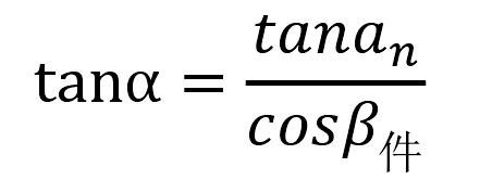
Where, 𝑎 n is the normal pressure angle of the tool; 𝛽 part is the spiral rise angle of gear workpiece.
As shown in the figure, the mapping error of tool profile error on gear end face:
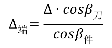
Where: the cutting tool is the spiral angle of the cutting tool; The workpiece is the helix angle of the workpiece.
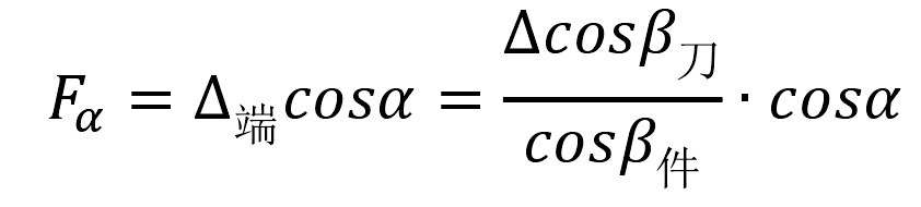
Then, the gear profile error is obtained: