Both helical gear 1 and helical gear 2 are linear elastic materials. The young’s modulus of helical gear 1 is 190000000000pa, Poisson’s ratio is 0.31, and the density is 7850kg / m3; Similarly, helical gear 2 is set to the same material.
(1) Set contact pairs
For the convenience of analysis and calculation, the helical gear profile is selected through the namedselection setting, in which the profile of helical gear 1 is the contact surface Ca, and the outer profile of helical gear 2 is the target surface, in which the contact type is set as frictionless contact.
(2) Define helical gear pair
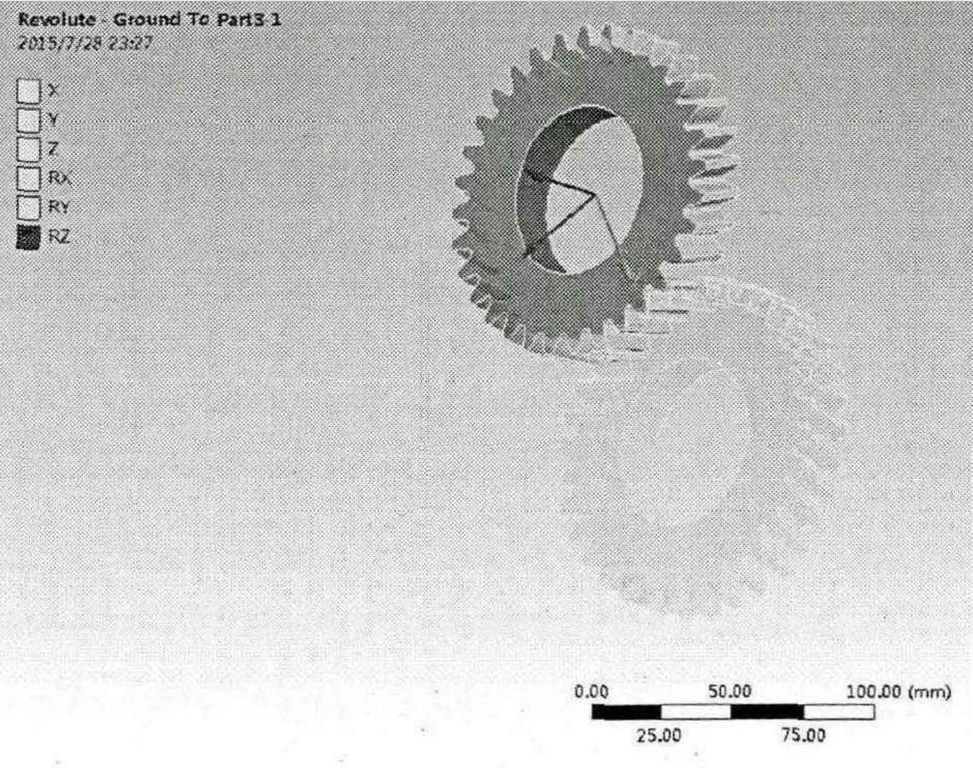
Right click “connections” and select insertjoint. The “connection details” setting panel will appear in the details window. Set “connectiontype” to “body – ground”, hinge type to “revolve”, and select the inner hole surface of helical gear 1. As shown in the figure, the well-defined smart gear rotating pair shows that the helical gear has only rotational freedom and rotates around the z-axis. Similarly, the rotating pair of another helical gear is defined.

(3) Boundary condition loading
Constrain the translational displacement of helical gear 2, apply a rotating speed of 25rad / s on helical gear I, the two helical gears are in friction contact, the friction coefficient is 0.1, and apply a resistance moment of 80000n, mm on the driven gear. The calculation time is 15s.
