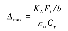
Tooth profile modification is a common method to avoid the impact of gears in the process of meshing. It can make the size of the base joint of the master and slave gears the same by purposefully removing some materials on the tooth surface, so as to improve the transmission performance. The schematic diagram of gear profile modification is shown in Figure 5. The tooth profile modification parameters are mainly composed of three factors: the maximum modification amount Δ max, the modification length L and the modification curve. As there is no unified formula to calculate the maximum modification Δ max, two methods are usually used to determine 297-299. The modification is determined according to the deformation of the loaded gear teeth or the accuracy level of the driving and driven wheels. The empirical formula is used in this paper

Where, Ka is the working condition factor; ft is the circumferential force, N; B is the tooth width, mm; ε α is the end face coincidence degree; C γ is the stiffness, N / (mm · μ m): K A is the working condition factor; f t is the circumferential force, n; B is the tooth width, mm; e α is the end face coincidence degree; C γ is the stiffness, N / (mm · μ m): K A is
The position of the starting point of the modification depends on the length of the modification. The length of the modification is generally divided into long modification and short modification. The application of the two is different. The long modification is mainly used in the modification, as shown in Figure 5 As shown in the figure, the modification length of long modification refers to the distance from the highest point of the single tooth meshing area to the tooth top, and the modification length of short modification refers to the distance from the highest point of the single tooth meshing area and the midpoint of the tooth top to the tooth top. The formula of modification length is as follows:
Long modification

Short practice

Where Pb is the pitch of base circle, mm.
The commonly used modification curves are straight line, parabola, hyperbola, etc. The linear modification equation is

The parabolic modification equation is

Where, X is the relative coordinate of the meshing position, along the direction of the meshing line, the origin of the coordinate takes the position of the alternate point of the single and double teeth meshing; Δ is the modification amount at x, μ M.


