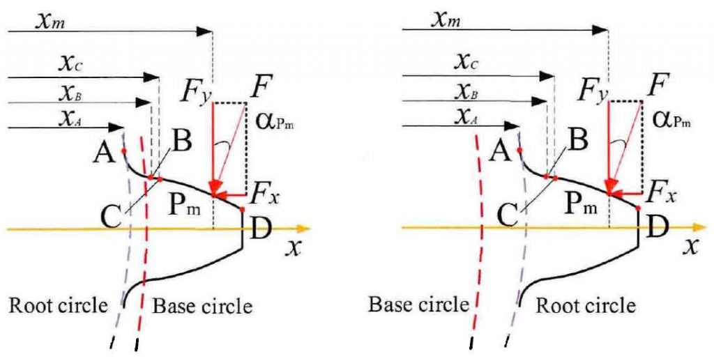
(b) The base circle is smaller than the root circle
In order to further study the dividing line of the number of teeth in the two cases, according to the basic parameter expression of the base circle and the root circle, the standard involute parameters, i.e. the pressure angle a = 20 °, the coefficient of addendum height h * a = L and the coefficient of addendum clearance C * = 0.25, are taken for calculation and analysis, and the radius curves varying with the number of teeth are drawn for comparison Fig. It can be seen from Figure 2 that with the increase of the number of teeth, the root circle gradually changes from less than the base circle to greater than the base circle. When the number of teeth is larger, the base circle is larger than the root circle, which is consistent with the situation shown in Figure 1 (a); when the number of teeth z > 41, the base circle is smaller than the root circle, as shown in Figure 1 (b). In view of these two different gear geometric effects, the following will select the gear pair under different conditions for the simulation calculation of tooth stiffness.

According to the introduction of gear tooth profile composition, it is assumed that the initial meshing point is not from point B, but from point C, that is, point C is the initial meshing point B2. Thus, the BD segment of the involute curve can be further divided into non meshing segment BC and meshing segment CD. In order to verify the correctness of this hypothesis, the meshing angle parameters of meshing initial point B2 and involute curve initial point B or the radius of the line between OB and ob2 are compared and analyzed. The formula of meshing angle and radius related to point B2 and point B is as follows:

The simulation results of the formula are drawn in Fig. 3. The results show that the change of the meshing angle with the number of teeth at the initial meshing point is greater than that at the initial point B of the involute curve, and the difference between the two radii is small but greater than 0, and presents the curve change effect of first increasing and then decreasing. According to the different meshing effects, the complete gear tooth profile can be divided into three parts: ab section of fillet transition curve, BC section of non meshing zone and CD section of meshing zone. According to the results of hypothesis verification, the stiffness components of gear tooth stiffness can be further analyzed and studied in sections. Combined with the formula, the detailed formulas of compression stiffness Ka, bending stiffness KB and shear stiffness KT are derived.


