
1. Part drawing analysis
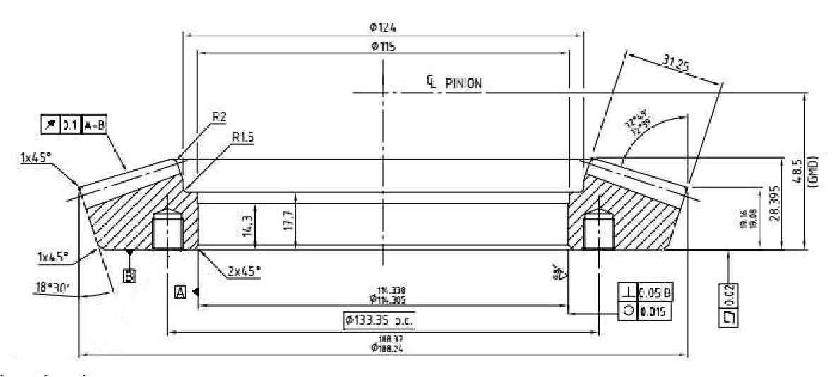
Figure 1 is the part drawing of the driven spiral bevel gear of the rear axle of an automobile. As shown in the figure, the shape of spiral bevel gear is more complex than that of ordinary spiral bevel gear because of the existence of gear bevel angle and tooth profile helix angle, so the local material fluidity in the forming process will be very poor, and it is easy to have poor local material flow in the forming process, resulting in insufficient filling of the die cavity. Therefore, the processing and forming of the tooth shape area is the key and difficult point of the manufacturing process of the part. As the spiral bevel gear is required to be formed near the end, the tooth shape part is as few as possible, there is no subsequent machining, and the forming quality requirements are strict, so the spiral bevel gear part must be formed in the forging process. The key problem of forming the tooth profile of the part is whether the tooth profile can fill the tooth profile mold cavity perfectly and whether there will be casting defects such as burrs.
2. Determination of forging drawing of driven spiral bevel gear
2.1 Determination of cold forging drawing
Determination of parting surface
The determination of parting surface mainly considers the following factors:
(1) The forging can be easily loaded and unloaded from the die bore;
(2) Metal can fully fill the mold bore;
(3) Reduce the number of remaining blocks and the probability of burrs;
(4) Reducing die forging process steps is conducive to simplifying die manufacturing process.
Based on the above analysis and the structural characteristics of spiral bevel gear, it is determined that the maximum outer diameter of the gear is the parting surface.
Determination of dimensional tolerance and machining allowance of forgings
According to the technical roadmap of this paper, the tooth shape part of the workpiece can first form the basic contour through the casting process, and then modify the tooth shape part through the closed hot die forging step. The final cold precision forging process can ensure that the dimensional accuracy and surface quality meet the requirements of finished parts. Therefore, the tooth shape part does not need machining, so there is no mechanical machining
Spare time. Considering the subsequent need to tap the threaded hole on the bottom surface of the spiral bevel gear, it is necessary to reserve a machining allowance of 1mm on the bottom surface of the spiral bevel gear according to the relevant process requirements. Referring to the contents in 2003-12362 GB / T, it can be obtained that the spiral bevel gear studied belongs to 4S grade complex forging; The material coefficient is 1m, from which the dimensional tolerance of each part of the forging can be obtained by referring to the table.
Die forging slope
The tooth surface of the driven spiral bevel gear itself is a certain taper, that is, there is a natural die forging inclination, so it can be easily removed from the die without adding another die forging inclination.
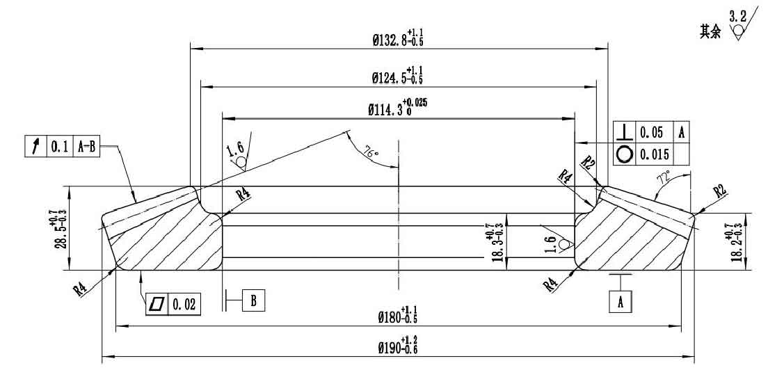
Through the above analysis, it is determined that the cold forging drawing of driven spiral bevel gear is shown in Figure 2.
2.2 Determination of hot forging drawing
Based on the cold forging drawing, the dimensions of the hot forging drawing are determined by comprehensively considering the factors such as material shrinkage and dimensional tolerance. Therefore, the drawing of cold forging needs to be thermally scaled. The shrinkage rate of alloy steel forging is 1 ~ 1.5%. The material 20CrMoH used in the forging belongs to low alloy steel, so the scaling coefficient is 1.012. The dimensional tolerance can be obtained by referring to 2003-12362 GB / T.
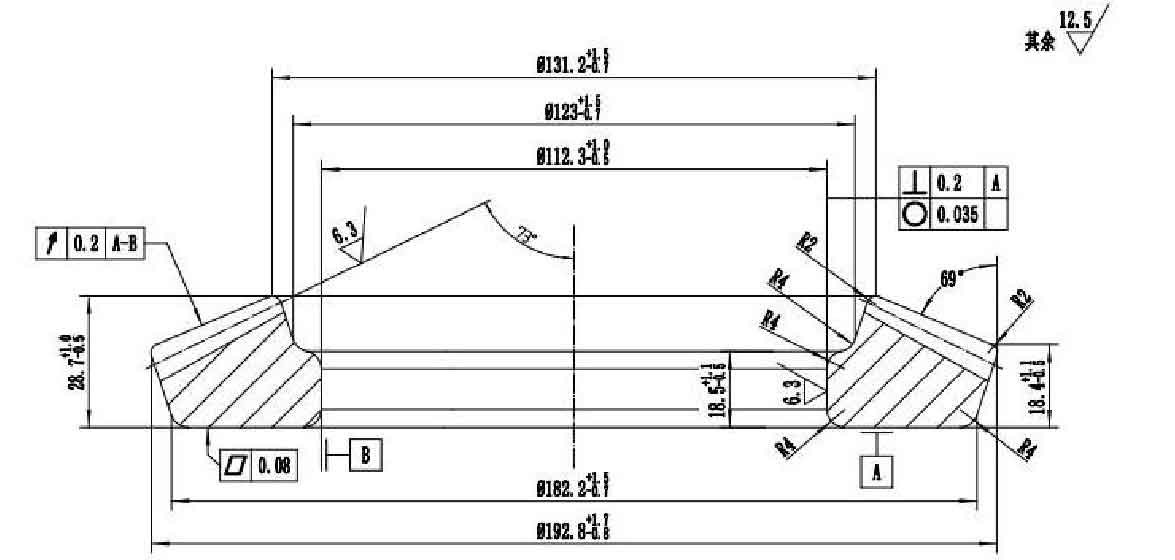
Through the above analysis, it is determined that the drawing of hot forging is shown in Figure 3.