
In the small-batch production of a specific wind turbine gearbox sun gear, a significant quality issue was consistently observed post-heat treatment. After the final gear grinding operation, a slight step appeared at the tooth root near both ends of the gear face width. Concurrently, the central region of the tooth flank exhibited insufficient grinding allowance, resulting in unremoved material or “black skin,” ultimately causing the span measurement (W4) to exceed tolerance limits. In severe cases of distortion, the central area lacked sufficient stock entirely, leading to scrapped components. This problem severely impacted product yield, delivery schedules, and manufacturing costs. Analysis indicated that this distortion pattern leads to non-uniform grinding allowance, which subsequently causes uneven surface hardness and effective case depth after grinding. This non-uniformity compromises the gear’s contact strength, load-bearing capacity, and fatigue strength at the root steps, ultimately reducing the gear’s service life.
The subject component is a sun gear shaft made from 18CrNiMo7-6 steel. Its key specifications are: module mn=15mm, number of teeth Z=24, pressure angle α=25°, face width B=388mm, and a specified span measurement W4 of 163.468–163.546 mm after final grinding. The carburizing and quenching process requires a tooth surface hardness of 58–62 HRC and an effective case depth of 2.5–3.0 mm. The original process route was: Forging → Post-forging Heat Treatment → Rough Turning → Ultrasonic Testing (UT) → Semi-Finish Turning → Gear Hobbing → Heat Treatment (Carburizing & Quenching) → Finish Turning → UT → Deep Hole Drilling → Cylindrical Grinding → Spline Rolling → Gear Grinding → Inspection.
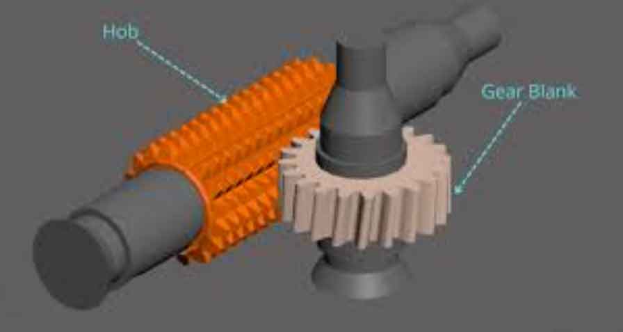
For the initial gear hobbing process, the span measurement was set to W4_hob = 164.16 mm, leaving a nominal grinding allowance of ΔW = 0.66 mm on the diameter. A protuberance hob was used to prevent a grinding step at the tooth root. Post-heat treatment measurements of the span were taken at eight axial locations (approximately every 65mm along the face width, starting 15mm from the end), with three points measured circumferentially at each location. The averaged data revealed a distinct “saddle” or “hourglass” distortion pattern, as summarized in the table below.
| Axial Measurement Position (from end) | Avg. Span W4_post-HT (mm) | Change from Hobbed Size Δ (mm) |
|---|---|---|
| 15 mm (End Region) | 164.35 | +0.19 |
| 65 mm | 164.22 | +0.06 |
| 115 mm | 164.04 | -0.12 |
| 165 mm | 163.93 | -0.23 |
| 215 mm (Center Region) | 163.87 | -0.29 |
| 265 mm | 163.92 | -0.24 |
| 315 mm | 164.03 | -0.13 |
| 365 mm | 164.12 | -0.04 |
The data shows significant expansion (up to +0.19 mm) near the ends and contraction (up to -0.29 mm) in the central region. The total peak-to-valley variation was 0.51 mm, implying a single-side variation of approximately 0.26 mm. Pre-grinding alignment checks confirmed this, showing excessive stock at the ends and insufficient stock in the center, leading to the described quality defects.
The primary cause of this distortion is the interplay of thermal and transformation stresses during quenching. For a long, slender shaft-like component such as this sun gear, transformation stresses (or phase change stresses) often dominate. During rapid cooling, the surface transforms to martensite first. The subsequent expansion due to the larger specific volume of martensite is constrained by the hotter, softer core, setting up complex stress states. For a component with a relatively small controlling cross-section, this typically results in a saddle-shape distortion: contraction along the length (in this case, reduction in span measurement) accompanied by slight expansion at the free ends. The ends, having a smaller thermal mass, can cool and transform more completely, leading to greater martensitic expansion relative to the central bulk.
The distortion can be modeled conceptually. The resultant change in span measurement ΔW(x) along the axis x can be thought of as a superposition of a parabolic contraction and end effects:
$$
\Delta W(x) = -A \left(1 – \frac{4x^2}{L^2}\right) + B e^{-k|x|}
$$
where L is the effective heated length, A represents the amplitude of central contraction, and the exponential term B e^{-k|x|} models the localized expansion near the ends (x=0 and x=L). The net observed profile is the sum of these effects.
The consequences are severe:
- Non-uniform Effective Case Depth: To grind the tightest point (center), excess material must be removed from the ends. This removes more of the hardened case at the ends, making the effective depth shallower there compared to the center. The differential removal of ~0.26 mm per side directly reduces case depth at the ends.
- Non-uniform Surface Hardness: The hardness gradient below the surface is steep. Removing only 0.1 mm at the center might achieve the required 59-60 HRC, but removing 0.6 mm at the ends could drop the hardness below the 58 HRC specification, as material from a deeper, lower-hardness region is exposed.
- Reduced Fatigue Strength: The root step acts as a stress concentrator, initiating fatigue cracks.
- Low Grinding Efficiency & Yield: The grinder must slowly navigate the uneven stock, and parts with extreme center contraction become scrap.
Several corrective actions were considered:
- Adding Process Extensions: Attaching sacrificial material to the ends to increase thermal mass and reduce end expansion. This adds material cost and requires an extra machining step for removal.
- Increasing Overall Hobbing Allowance: A common but suboptimal industry practice. It ensures the minimal point has enough stock but exacerbates the problems of end steps, case depth variation, and hardness non-uniformity.
- Compensatory Crown in Gear Hobbing: Utilizing the CNC capabilities of the modern hobbing machine to introduce a deliberate crown (or “barrel shape”) on the hobbed teeth. This pre-distortion, opposite to the expected heat treatment distortion, aims to result in a more uniform post-heat treatment shape. This method leverages existing equipment, adds no extra cost per piece, and directly addresses the root cause of the quality issues.
The third option was selected for its direct effectiveness and efficiency. The goal is to modify the gear hobbing process to produce a tooth profile that, after distortion, becomes nearly straight. Based on the measured distortion data, the maximum single-side contraction was ~0.15 mm at the 215 mm position from one end. Factoring in the ~0.1 mm end expansion, a symmetrical crown was programmed. Since the CNC machine typically applies a symmetrical crowning profile, the total compensation was designed over a virtual length of 430 mm to ensure the 215 mm point from each end received the full correction. The principle is to command a negative crown during gear hobbing to offset the positive crown caused by heat treatment.
The modified hobbing process was executed, and the span was measured. The results confirmed the intended pre-correction profile, with the largest span in the center and smaller values towards the ends, perfectly inverting the expected post-HT shape.
| Axial Measurement Position (from end) | Avg. Span W4_Modified-Hob (mm) | Profile (Relative to Ends) |
|---|---|---|
| 15 mm (End Region) | 164.19 | Lower |
| 65 mm | 164.23 | Higher |
| 115 mm | 164.26 | Higher |
| 165 mm | 164.29 | Higher |
| 215 mm (Center Region) | 164.33 | Highest (+0.14 from ends) |
| 265 mm | 164.29 | Higher |
| 315 mm | 164.24 | Higher |
| 365 mm | 164.20 | Lower |
After heat treatment, the same component was measured again. The results demonstrated a dramatic improvement in uniformity.
| Axial Measurement Position (from end) | Avg. Span W4_post-HT (mm) | Change from Modified Hob Δ (mm) |
|---|---|---|
| 15 mm | 164.16 | -0.03 |
| 65 mm | 164.14 | -0.09 |
| 115 mm | 164.11 | -0.15 |
| 165 mm | 164.09 | -0.20 |
| 215 mm | 164.07 | -0.26 |
| 265 mm | 164.06 | -0.23 |
| 315 mm | 164.08 | -0.16 |
| 365 mm | 164.09 | -0.11 |
The peak-to-valley variation was reduced from 0.51 mm to just 0.14 mm, a 73% improvement. The single-side variation was now approximately 0.07 mm. Pre-grinding alignment checks showed a remarkably uniform stock distribution across the face width, with all measured points having sufficient and similar allowances. The subsequent gear grinding process successfully produced teeth without root steps or unground patches. The final span measurement was within the tight specification of 163.468–163.546 mm.
The success of the compensatory gear hobbing can be quantified. Let C_target be the required crown during hobbing. It can be estimated from the distortion data ΔW_original(x):
$$
C_{target}(x) \approx -\Delta W_{original}(x) + \delta
$$
where δ is a small safety margin. In practice, for a symmetrical correction on a symmetrical part, the machine’s crowning function, often a parabolic modification Δs, is applied:
$$
\Delta s(x) = -E \left( \frac{2x}{L} – 1 \right)^2 + E
$$
where E is the crown amplitude parameter set in the CNC hobbing program, L is the active length for crowning, and x is the axial position. The optimal E is found iteratively or based on prior data, as was done here (E corresponding to ~0.15 mm single-side correction).
The benefits are multifaceted and significant:
- Uniform Grinding Allowance and Case Depth: The post-HT span variation of 0.14 mm (0.07 mm/side) ensures nearly uniform material removal during grinding. This preserves a consistent and specification-compliant effective case depth across the entire face width.
- Uniform Surface Hardness: With uniform stock removal, the final surface consistently lies within the high-hardness region of the hardness gradient curve. Assuming a hardness gradient H(d) where d is depth, the final hardness H_final is:
$$
H_{final} \approx H(\Delta r)
$$
where Δr is the uniform removal. Since Δr is now nearly constant, H_final is uniform, meeting the 58-62 HRC requirement everywhere. - Elimination of Stress Raisers: The absence of a root step removes a potent stress concentration factor, directly enhancing bending fatigue strength.
- Dramatic Increase in Grinding Efficiency: The grinding time was reduced from 3.6 hours to 2.6 hours per component, a 28% productivity gain, because the machine no longer needs to carefully navigate large stock variations.
- Improved Yield and Cost Reduction: The virtual elimination of scraping due to excessive distortion directly improves yield and reduces overall unit cost.
This process improvement, centered on intelligent pre-compensation during gear hobbing, has proven to be a robust and effective solution. The methodology has since been successfully applied to other shaft-like gears, particularly long pinions and gears with face widths exceeding 300 mm. It represents a practical application of “right-first-time” manufacturing philosophy, where understanding and anticipating process physics (heat treatment distortion) allows for a simple yet powerful corrective action in a preceding machining step (gear hobbing). The key enabler is the advanced capability of modern CNC hobbing machines to apply sophisticated profile modifications, turning a standard machining process into a strategic tool for quality assurance and performance enhancement.