
When the complex data of logarithmic spiral bevel gear tooth surface is obtained by laser scanner, the accuracy of data acquisition must be considered. Inevitably, due to the influence of light reflection, environmental noise and other factors, some unnecessary data points are brought. In addition, the collected point cloud is too miscellaneous. If the measured data is directly used for curve and surface modeling, it is bound to cause large surface data error, low accuracy, and even interference, warpage and other deformation of the fitting surface.
Therefore, it is necessary to preprocess the measured data before the tooth surface reconstruction of logarithmic spiral bevel gear according to the geometric characteristics and generation law of logarithmic spiral bevel gear. It mainly includes the location of noise points, data smoothing, data simplification, etc.
Imageware software is used to process the data points on the tooth surface of logarithmic spiral bevel gear. Imageware is produced by EDS company of the United States, later acquired by Siemens PLM Software of Germany, and now incorporated into its NX product line. It is the most famous reverse engineering software. Because of its strong point cloud processing ability Surface editing ability and class a surface construction ability are widely used in the design and manufacturing fields of automobile, aviation, aerospace, consumer appliances, molds, computer parts and so on. Imageware adopts NURBS technology. The software is powerful and easy to apply. Imageware products provide unique and comprehensive free-form surface modeling and testing. The products will develop to modularity and have four core competitiveness: advanced surface, three-dimensional measurement, modeling and reverse engineering. Imageware has low requirements for hardware and can run on various platforms: Unix workstation and PC, and the operating system can be UNIX, NT, Windows95 and other platforms.
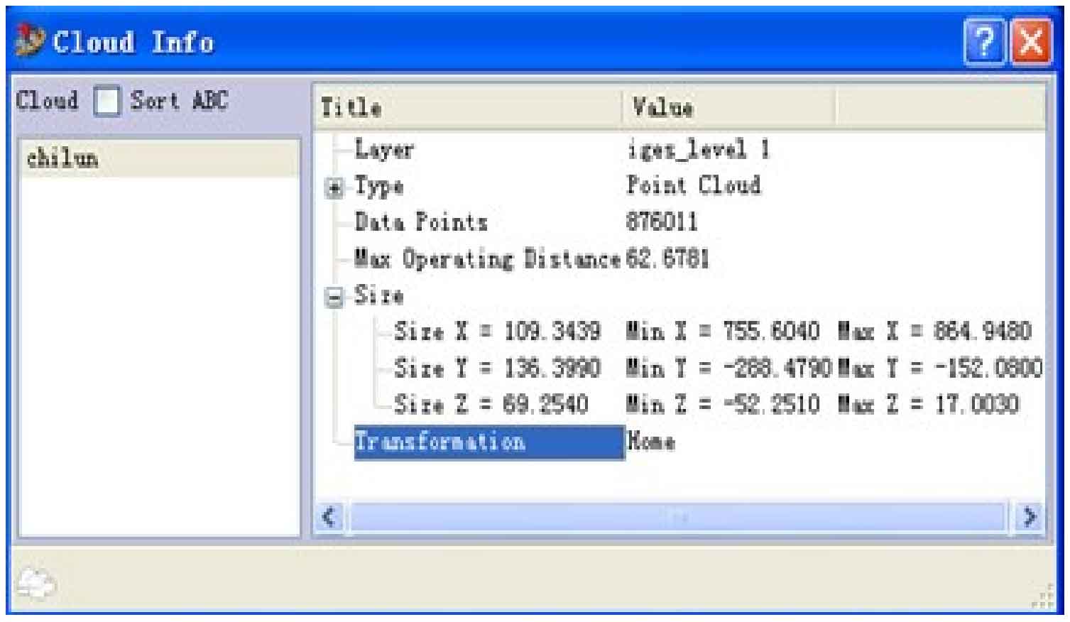
Start Imageware, click the open button on the toolbar, read in the scanned logarithmic spiral bevel gear point cloud data, and use the shortcut key Ctrl + I to open the point cloud information command dialog box, as shown in Figure 1. The following information is obtained: the point cloud contains 876011 points, the maximum span of the point cloud is 62.6781, and the distribution span in spatial x, y and Z coordinates. It can be found that the point data contained in the point cloud is too large, and the amount of point cloud needs to be reduced.
Close the information dialog box, click the menu command modify → datareduction → space sampling, select chilun in the pop-up command dialog box, select with distance in the mode bar, enter the distance error of 0.5 in the distance tolerance bar, and click apply. The distance error here varies according to the requirements for the accuracy of the sample. Generally, it is required to be 0.15-0.5. Enter 0.5 in the distance column (the greater the value, the less the point cloud will be obtained). After the operation of reducing the point cloud data, the calculation results are displayed in the result column of the command dialog box. The point cloud data is reduced from the original 876011 points to 118306 points, reducing 86% of the original point cloud. This processing can increase the speed of other operations.
Visualize the point cloud, that is, polygonize the point cloud, so as to view the effect after the point cloud is formed. Use the menu command construct → polygon mesh → polygon cloud to get a command dialog box. Display the point cloud name chilun in the cloud column, set the distance of polygonized point cloud 0.50 in the neighborhood size column, and click the middle mouse button to confirm. Press and hold the left mouse button and move the mouse to adjust the view of the system to the front view position.
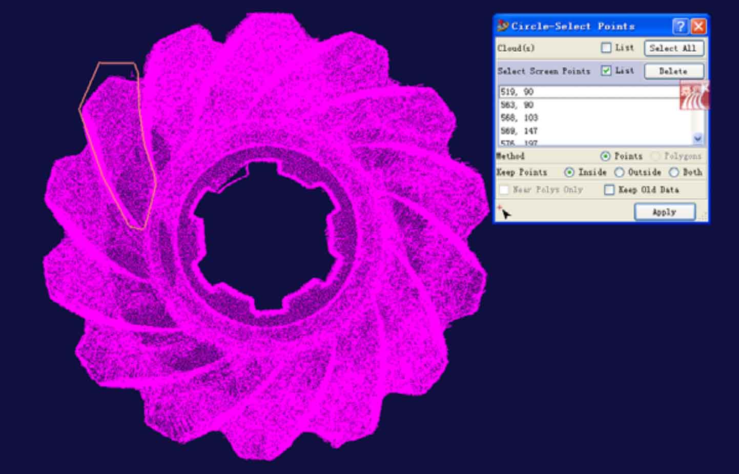
Check whether there are redundant noise points around the point cloud. If there are noise points, you can use the menu command modify → scan line → pick delete points to delete unnecessary points in turn. Use the menu command modify → extract → circle select points to get the circle select points command dialog box. Select the both option in the keep points column to split the point cloud and keep the rest of the point cloud. Click the select screen points column, and then click the position in the view as shown in Figure 2. Click the middle key to confirm, the system will name the automatically generated point cloud chilun in and chilun out, and save the extracted logarithmic spiral bevel gear tooth surface data point cloud in chimian to prepare for future logarithmic spiral bevel gear tooth surface reconstruction.
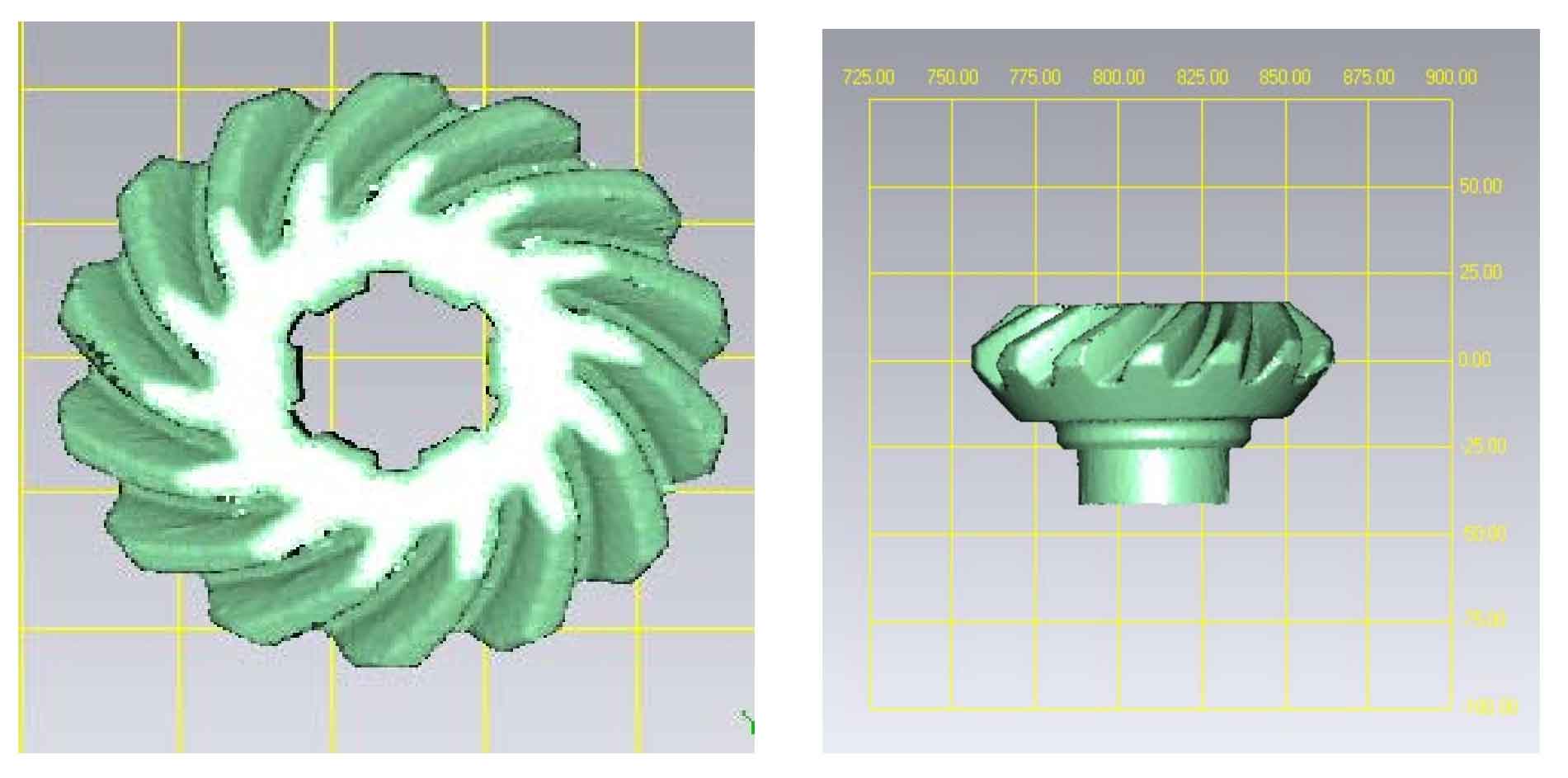
After a series of point cloud processing, the point cloud effect of logarithmic spiral bevel gear as shown in Figure 3 is obtained.