
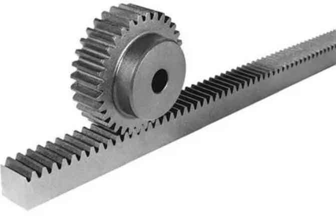
Rack and pinion gears are a common type of gear system used to convert rotary motion into linear motion or vice versa. The system consists of two main components: the rack, which is a straight toothed bar, and the pinion gear, which is a cylindrical gear with teeth. Understanding the geometry and operation of rack and pinion gear design is essential for their successful implementation. Here’s a simplified explanation of the design and operation:
Geometry:
- Rack: The rack is a straight bar with parallel toothed grooves along its length. The teeth on the rack are designed to mesh with the teeth on the pinion gear. The rack’s shape and size depend on the specific application and required linear motion.
- Pinion Gear: The pinion gear is a cylindrical gear with teeth that mesh with the teeth on the rack. The teeth are evenly spaced around the circumference of the gear. The number of teeth on the pinion gear determines the gear ratio and the amount of linear motion generated for each revolution.
Operation:
- Rotary-to-Linear Motion: When the pinion gear rotates, its teeth engage with the teeth on the rack, causing the rack to move linearly. The direction of the linear motion depends on the rotational direction of the pinion gear. As the pinion gear continues to rotate, the rack moves proportionally, providing linear motion.
- Linear-to-Rotary Motion: In applications where the rack is fixed, applying linear motion to the rack causes the pinion gear to rotate. The rotation of the pinion gear is directly proportional to the linear displacement of the rack. This mechanism is often used in applications where linear input motion needs to be converted into rotary motion.
Key Design Considerations:
- Tooth Profile: The teeth on both the rack and pinion gear are typically designed with an involute tooth profile, which allows for smooth engagement and reduces backlash.
- Module and Pitch: The module (for metric) or pitch (for imperial) refers to the size of the teeth on the gear. It determines the dimensions and spacing of the teeth, and is an important consideration in the design process.
- Gear Ratio: The gear ratio is determined by the number of teeth on the pinion gear relative to the rack. It determines the relationship between the rotational motion of the pinion gear and the linear motion of the rack.
- Backlash: Backlash refers to the slight clearance or free movement between the teeth of the rack and pinion gear when the direction of motion changes. Minimizing backlash is crucial for achieving precise and controlled motion.
Rack and pinion gear design requires careful consideration of factors such as tooth profile, module/pitch, gear ratio, and backlash. These design considerations ensure smooth and efficient operation, accurate linear motion, and reliable performance in various applications.