
The normal profile is scanned according to the spiral guide line to generate the helical gear profile surface, and then the surface is used as the boundary to cut the solid, and the remaining solid is the helical gear tooth solid.
1.Scanning normal surface contour
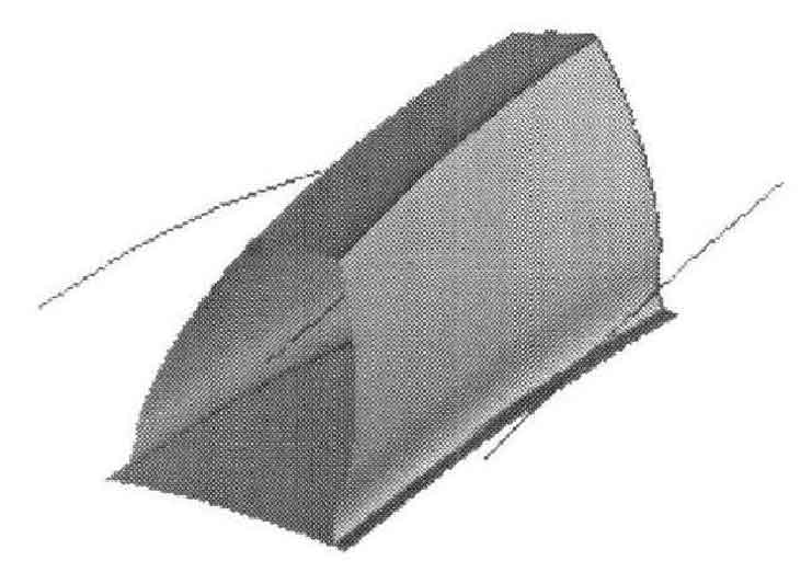
Rotate the coordinates back to the original position. According to the scanning mode of free-form surface in UG, select three guide lines in the object window, then select the normal tooth profile, and select the arc length alignment mode in the alignment mode to obtain the surface as shown in Figure 1.
2.Single tooth entity generation
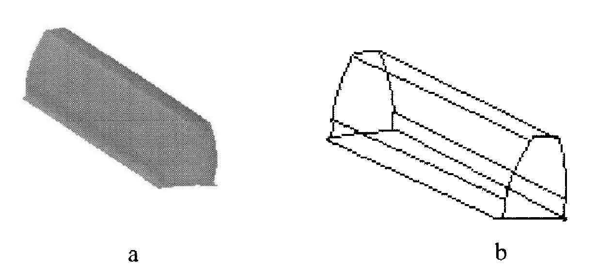
Move the coordinates along the Z-axis by 10 and draw a square entity whose length in the z-axis direction is the tooth width B. Use the generated teeth to cut it to obtain a single oblique tooth, as shown in Figure 2. It can be seen that the normal plane intersects with the end face. If the square entity is drawn from the origin of the original coordinate, the scanned single tooth surface does not pass through the two opposite sides of the square, and the cutting operation cannot be completed.
3.Realization of helical gear
Draw the tooth root cylinder with the tooth width as the height, perform Boolean addition operation on the tooth and cylinder, and array the number of tooth features with the rotation angle of. The results are shown in Figure 3.
