
In the process of localizing critical components for imported rail vehicles, the development of a high-performance spiral bevel gear pair emerged as a paramount engineering challenge. This gear pair, characterized by its equal depth teeth, serves as the core transmission element within the axle gearbox, responsible for powering onboard auxiliary systems. The successful reproduction of this component required not only precision machining but, more critically, the mastery of advanced heat treatment processes to achieve the necessary metallurgical properties while meticulously controlling dimensional stability and preventing detrimental heat treatment defects. This account details the comprehensive technical journey, from design interpretation to final validation, focusing on the methodologies employed to ensure quality and reliability.
Functional Role and Design Specifications
The equal-depth spiral bevel gear pair is installed in the central axle gearbox of a bogie. Its primary function is to transmit rotational power from the wheelset to a generator via a universal joint and couplings, thereby supplying electricity for coach air conditioning systems. In this configuration, the larger gear acts as the driving component, while the smaller gear is driven, operating at a significant speed ratio to deliver the required power at rated conditions. The success of this power transmission relies entirely on the geometric accuracy and material integrity of the gears, which are susceptible to failure if heat treatment defects such as excessive distortion, soft spots, or grinding cracks are present.
The key design parameters, which established the baseline for all manufacturing and quality control activities, are summarized below:
| Parameter | Large Gear (Driving) | Small Gear (Driven) |
|---|---|---|
| Gear Type | Spiral Bevel, Equal Depth Tooth | Spiral Bevel, Equal Depth Tooth |
| Number of Teeth (z) | 34 | 11 |
| Spiral Direction | Right Hand | Left Hand |
| Module (mn / mm) | 6 | 6 |
| Pressure Angle (α / °) | 20 | 20 |
| Mean Spiral Angle (β / °) | 35 | 35 |
| Shaft Angle (Σ / °) | 90 | |
| Material | 18CrNiMo7-6 | 16MnCr5 |
| Required Case Hardness (HRC) | 58-62 | 58-62 |
| Required Core Hardness (HRC) | 30-40 | 30-40 |
| Manufacturing Accuracy Grade | ||
Manufacturing Process and Critical Machining
The manufacturing sequence was carefully planned to ensure cumulative accuracy, with particular attention paid to stages preceding final heat treatment, as these directly influence the propensity for subsequent heat treatment defects.
1. Gear Tooth Cutting: The spiral bevel teeth were generated using a dedicated gear cutting machine with a single-sided cutting method. A 6-inch diameter dual-face cutter head was employed. Specialized fixtures were crucial for maintaining positional accuracy during cutting and later during pairing inspection. The large gear was located and clamped using its inner bore diameter and a front face. The small pinion, being a shaft-type component, was secured using its long journal centers and a drawbolt mechanism. This precise fixturing minimizes runout and misalignment, which can be exacerbated during heat treatment, leading to unacceptable heat treatment defects like non-uniform case depth or distortion.
2. Pre-Heat Treatment (Optimization): Prior to carburizing, both gear materials underwent a quenching and high-temperature tempering process (i.e., conventional hardening and tempering). This step serves multiple vital functions: it refines the grain structure of the core material, relieves internal stresses from forging and machining, and establishes a uniform, fine-grained sorbitic structure. This preparatory structure is essential as it enhances the hardenability of the core during the final quench, promotes a more uniform case-core transition, and significantly reduces the risk of catastrophic heat treatment defects such as quench cracking or excessive volumetric change. The relationship between prior structure and quench susceptibility can be conceptualized by the hardenability factor, which is influenced by grain size. A finer prior austenite grain size ($$ASTM\ No. \geq 6$$) generally leads to better toughness and less distortion.
The Pivotal Heat Treatment and Distortion Control Strategy
Heat treatment is the most critical phase in manufacturing these high-performance gears. The primary objectives were to achieve a high surface hardness for wear resistance, a tough core for fatigue strength, and a controlled carburized case depth—all while maintaining strict geometric tolerances. The threat of heat treatment defects, primarily distortion, loomed large, especially for the thin-walled, large-diameter ring gear.
1. Copper Plating for Selective Carburizing: To prevent carburization on non-functional surfaces (e.g., bores, specific faces), a copper electroplating process was applied before gas carburizing. This acts as a physical barrier against carbon diffusion. Any failure in this coating, such as porosity or peeling, would result in a local heat treatment defect characterized by unintended hardening, complicating subsequent machining and potentially creating stress concentration points.
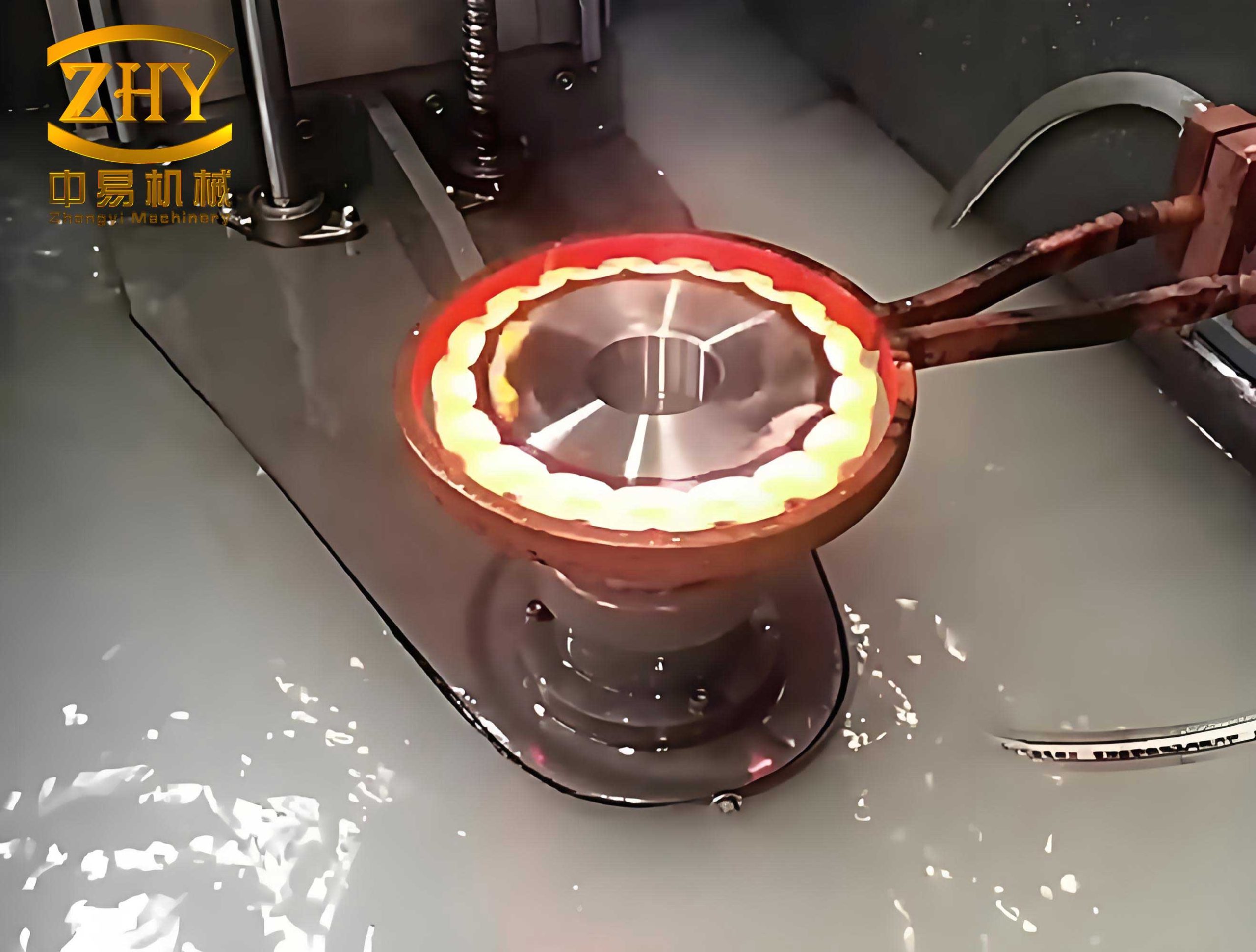
2. Press Quenching of the Large Gear: To actively combat distortion, the large gear was subjected to a press quenching operation. A custom-designed quenching die was manufactured, comprising an outer conical ring (matching the tooth crown cone), an inner vertical pressure ring, and a central expanding mandrel (collet-type). The process, executed on an automated quenching press, is summarized by the following critical parameters designed to balance cooling rate and stress minimization:
| Process Parameter | Value / Setting |
|---|---|
| Outer Ring Pressure (1st Stage) | 80 – 100 bar |
| Inner Ring Pressure (1st Stage) | 60 – 80 bar |
| Expander Pressure | 30 – 50 bar |
| Oil Flow Rate (Quenchant) | Setting 3 |
| Total Quench Time | 180 s |
The sequence is vital: The hot gear is rapidly transferred to the press, centered by the expanding mandrel, and immediately clamped by the outer and inner rings before intensive oil quenching begins. This constrains the part’s ability to warp freely, forcing it to cool and transform within the confines of the die geometry. The cooling rate ($$V_{cool}$$) during this phase must be sufficiently high to form martensite in the case (avoiding soft pearlitic structures, a major heat treatment defect) but controlled enough to minimize thermal gradients and transformation stresses. The effectiveness of press quenching in suppressing out-of-roundness and face flatness errors is a direct measure of its success in mitigating distortion-related heat treatment defects.
3. Complete Heat Treatment Cycles: The full thermal processing schedules were meticulously developed.
For the Large Gear (Material: 18CrNiMo7-6):
1. Conventional Hardening and Tempering (QT): Austenitize ~860°C, oil quench, temper at high temperature (~600-650°C).
2. Copper plating on non-carburizing areas.
3. Gas Carburizing: Typically at 920-930°C to achieve a target case depth ($$CD_{eff} \approx 0.8 – 1.2\ mm$$). The case depth can be estimated by the empirical law: $$CD = k \sqrt{t}$$, where \(k\) is a temperature-dependent diffusion constant and \(t\) is time.
4. High-Temperature Tempering (to condition the case for machining).
5. Press Quenching: Re-austenitize at ~820-850°C, followed by the controlled die quench described above.
6. Sub-zero Treatment (e.g., -80°C) to transform retained austenite, stabilizing dimensions and increasing hardness.
7. Low-Temperature Tempering (~180-200°C) to relieve quench stresses without softening the martensite significantly.
For the Small Pinion (Material: 16MnCr5):
1. Conventional Hardening and Tempering (QT).
2. Protective coating application.
3. Gas Carburizing with Direct Quench: Carburize, then reduce furnace temperature to a suitable quenching austenitizing temperature (~840°C), and perform a vertical oil quench. Vertical hanging during carburizing and quench is critical to prevent bending distortion, a severe heat treatment defect for shaft components.
4. Low-Temperature Tempering.
The choice of tempering temperature ($$T_{temp}$$) is a compromise between toughness and hardness, often guided by the tempering parameter $$P = T_{temp}(C + \log t)$$, where \(C\) is a material constant and \(t\) is time in hours.
Comprehensive Quality Verification and Defect Analysis
Rigorous inspection was conducted at multiple stages to verify conformance and detect any potential heat treatment defects. The data from a representative manufactured pair is presented below, demonstrating the effectiveness of the controlled processes.
1. Dimensional Stability Before and After Heat Treatment: The primary metric for press quenching success. Measurements show significant control over distortion.
| Component & Measurement | Before HT (mm) | After Carburizing (mm) | After Press Quench & Tempering (mm) |
|---|---|---|---|
| Large Gear: Bore Roundness | 0.02 | 0.05 | 0.03 |
| Large Gear: Tooth Runout (Outer) | 0.04 | 0.08 | 0.05 |
| Large Gear: Face Flatness | 0.03 | 0.10 | 0.05 |
| Small Gear: Journal Runout | 0.02 | N/A | 0.04 |
The data confirms that while some distortion occurs during high-temperature carburizing, the press quenching operation effectively restores the geometry close to its pre-heat-treatment state, correcting a major potential heat treatment defect.
2. Achieved Metallurgical Properties: The core performance indicators.
| Property | Large Gear Result | Small Gear Result | Requirement |
|---|---|---|---|
| Effective Case Depth (mm) | 1.05 | 0.85 | 0.8 – 1.2 |
| Surface Hardness (HRC) | 60 | 61 | 58 – 62 |
| Core Hardness (HRC) | 36 | 34 | 30 – 40 |
3. Microstructural Evaluation: The definitive check for heat treatment defects at the microscopic level. Proper microstructure is non-negotiable for gear durability.
| Component & Zone | Required Structure | Observed Structure (Rating) |
|---|---|---|
| Large Gear: Case | Fine Martensite + Fine, Dispersed Carbides | Fine acicular martensite with少量 blocky/semi-networked carbides (Level 2-3) |
| Large Gear: Core | Low-Carbon Martensite/Bainite with minimal ferrite | Low-carbon martensite with minimal ferrite (Level 1) |
| Small Gear: Case | Fine Martensite + Fine, Dispersed Carbides | Fine acicular martensite with少量 granular carbides (Level 1-2) |
| Small Gear: Core | Low-Carbon Martensite/Bainite with minimal ferrite | Low-carbon martensite with少量 ferrite (Level 1) |
The “Level” refers to standard chart ratings for carbide size/distribution and free ferrite content. Levels 1-3 are generally acceptable for high-performance gears. The presence of retained austenite was minimized by the sub-zero treatment, preventing another common heat treatment defect that reduces contact fatigue strength.
4. Mechanical Properties: Tensile and impact tests on coupons from gear blanks verified the core material met standards, ensuring resistance to tooth bending fatigue and impact loads, failures often initiated by subsurface heat treatment defects like coarse microstructures or inadequate hardenability.
Validation Through Application
The final validation of the entire manufacturing process, and the confirmation that heat treatment defects were successfully avoided, came from rigorous testing. The manufactured gear pair was assembled into a complete axle gearbox. The gearbox first underwent a full-power bench test, operating at the rated power and speed for an extended duration without any signs of abnormal noise, vibration, or temperature rise. Subsequently, gearboxes were installed on operational passenger coaches and placed into revenue service on long-distance routes. After over a year of continuous operation, the performance and condition of the gearboxes were reported as excellent, with no failures or maintenance interventions required. This service history conclusively demonstrated that the manufacturing technology, with its stringent focus on controlling heat treatment defects, was fully capable of producing spiral bevel gears that met all design and functional requirements, achieving parity with the performance of the original imported components.