
The manufacturing of spiral bevel gears, critical components in aviation, maritime, and high-precision industrial machinery, is entirely dependent on specialized gear milling machines. The rotary table feed system of these machines typically employs gear transmission to execute position and velocity commands. To prevent jamming during meshing, a deliberate gap, known as backlash, exists between the tooth profiles of mating gears. However, this backlash introduces significant nonlinearity into the transmission system, severely degrading performance. It directly impacts the machining accuracy and stability of the gear milling machine, causing positional errors when the driving gear reverses direction before engaging the opposite flank of the driven gear. Furthermore, backlash can induce oscillatory behavior and impact loads between gears, accelerating wear. Therefore, eliminating or compensating for gear backlash is of paramount importance for the performance of CNC gear milling equipment.
This paper addresses this challenge by designing and implementing a dual-motor anti-backlash scheme based on a Programmable Multi-Axis Controller (PMAC). The core principle involves using two servo motors in a symmetric configuration to drive the load, coordinating their output torques to preload the gear train and eliminate free play. The study encompasses a thorough theoretical analysis of the anti-backlash process, the development of a dynamic mathematical model for the dual-motor drive system, the creation and analysis of a simulation model, and finally, the construction of an experimental platform for validation. Both simulation and experimental results confirm the effectiveness of the proposed approach in eliminating backlash and improving system performance.
Development Overview of Spiral Bevel Gear Milling Technology
The design and manufacture of spiral bevel gears represent a pinnacle of mechanical engineering complexity. Pioneered by companies like Gleason, the process requires sophisticated mathematical models and specialized machine tools. Modern CNC spiral bevel gear milling machines have evolved from purely mechanical systems to highly flexible, multi-axis CNC platforms. These machines abandon complex mechanical components like generating mechanisms in favor of digital interpolation and coordinated multi-axis motion, offering superior precision, flexibility, and ease of adjustment.
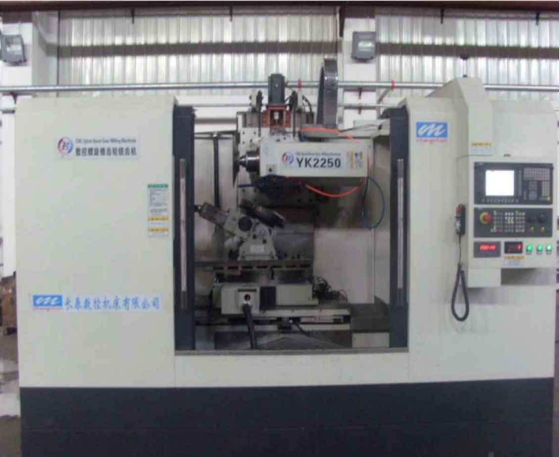
The numerical control (NC) system is the brain of such a gear milling machine. While high-end commercial systems from companies like Siemens or FANUC dominate the market, there is a strong impetus for developing open-architecture, proprietary NC systems to reduce costs and foster technological independence. The research presented here contributes to this goal by tackling a key subsystem challenge: the precision control of the rotary table’s feed drive, a common point where backlash limits overall gear milling accuracy.
Theoretical Analysis of Dual-Motor Anti-Backlash Drive Systems
Traditional mechanical anti-backlash methods, such as using spring-loaded split gears or adjusting center distance, often add complexity, reduce stiffness, and are susceptible to wear. The dual-motor drive method offers a more elegant and robust electronic solution. The system comprises two identical servo motors, each connected via a reducer to a pinion gear. Both pinions mesh with a single large output gear (or a rack in a linear analogy) that drives the load, such as a gear milling machine’s rotary table.
The fundamental principle is to control the two motors such that they apply opposing torques to the output gear, preloading the gear mesh. In the steady-state at rest, both motors apply a constant, equal, and opposite bias torque ($M_0$). This forces one pinion to contact the left flank of the output gear tooth and the other pinion to contact the right flank, effectively “clamping” the gear and removing all free play from the backlash zone ($2\alpha$).
Analysis of the Anti-Backlash Process
The system’s behavior during start-up and reversal is critical. The control strategy ensures that at least one pinion is always in contact with a gear flank, preventing the load from experiencing uncontrolled motion within the backlash gap.
Start-up Process (from rest to positive rotation):
- Initial Clamping: Motor A (master) and Motor B (slave) output torques $M_1 = +M_0$ and $M_2 = -M_0$, respectively. The net torque on the output gear is zero, but it is clamped.
- Acceleration: For a positive velocity command, $M_1$ increases positively, and $M_2$ decreases (becomes less negative). The net torque $M_{net} = M_1 – |M_2|$ becomes positive, accelerating the load. Both pinions remain in contact with opposite flanks.
- Transition: $M_2$ passes through zero. Pinion B disengages from the left flank, traverses the backlash gap, and engages the right flank.
- Co-driving: Both $M_1$ and $M_2$ become positive. Both pinions now drive the load on the same (right) flank, sharing the load torque.
Reversal Process: This involves a braking phase and a re-acceleration phase in the opposite direction. The master/slave roles swap. During braking, the torques decrease until $M_2$ becomes negative again, re-establishing the clamp across the backlash on the opposite flanks. Then, Motor B becomes the master for negative rotation, pulling the load through the reversal without any lost motion. The entire process for a sinusoidal position command, common in contouring operations for gear milling, can be summarized by the distinct meshing states in the table below.
| System Phase | Meshing State | Motor A Torque ($M_1$) | Motor B Torque ($M_2$) | Net Load Torque |
|---|---|---|---|---|
| At Rest (Clamped) | Opposite Flanks | +$M_0$ | -$M_0$ | 0 |
| Positive Acceleration | Opposite Flanks | Increasing + | Increasing (to 0, then +) | + |
| Positive Steady State | Same Flank (Right) | +$M_{drive}$ | +$M_{drive}$ | + |
| Positive Braking | Same to Opposite Flanks | Decreasing + | Decreasing + to – | – |
| At Rest Before Reverse | Opposite Flanks | +$M_0$ | -$M_0$ | 0 |
| Negative Acceleration | Opposite Flanks | Decreasing + | Increasing – | – |
Bias Torque Control Strategy
A practical and widely used control strategy, analogous to methods in commercial CNC systems like Siemens 840D, is implemented. In this scheme, only the master motor (e.g., Motor A) is under closed-loop position control from the PMAC. Its position controller output serves as the primary speed command. The slave motor (Motor B) receives the same speed command but with a small, controlled offset ($\Delta n$) introduced. This speed difference, processed through the drives’ current (torque) loops, generates the necessary bias torque. A Proportional-Integral (PI) compensator can be used to regulate this offset based on the torque or current difference between the two motors, ensuring stable bias torque maintenance and load distribution. The control structure is illustrated by the following key relationships for the motor voltage and torque balance during contact (for $\theta_c – i\theta_m > \alpha$):
Motor Electrical Equation:
$$ U = K_e \dot{\theta}_c + RI + L\dot{I} $$
Torque Balance for Pinion (e.g., Pinion 1):
$$ K_d I = J_c \ddot{\theta}_c + b_c \dot{\theta}_c + [k_s(\theta_c – i\theta_m – \alpha) + c_s(\dot{\theta}_c – i\dot{\theta}_m)] $$
Output Gear Dynamics:
$$ J_m \ddot{\theta}_m + b_m \dot{\theta}_m = i \cdot [k_s(\theta_c – i\theta_m – \alpha) + c_s(\dot{\theta}_c – i\dot{\theta}_m)] + \text{(Term from Pinion 2)} $$
where $K_e$ is back-EMF constant, $K_d$ is torque constant, $J_c$, $b_c$ are pinion inertia and damping, $k_s$, $c_s$ are transmission stiffness and damping, and $i$ is the gear ratio from pinion to output gear.
Dynamic Modeling of the Drive System with Backlash
To simulate and analyze the system, an accurate mathematical model incorporating backlash nonlinearity is essential. Among common models (Hysteresis, Dead-Zone, Impact), the Dead-Zone model is most suitable for control-oriented analysis of gear milling machine drives as it accounts for contact stiffness and damping.
The transmission torque $M_s$ across a gear pair with backlash $2\alpha$ is modeled as a dead-zone function of the angular displacement difference $\Delta \theta = \theta_d – \theta_f$ (for a single motor):
$$
M_s =
\begin{cases}
k_s(\Delta \theta – \alpha) + c_s \dot{\Delta \theta}, & \text{if } \Delta \theta > \alpha \\
0, & \text{if } |\Delta \theta| \le \alpha \\
k_s(\Delta \theta + \alpha) + c_s \dot{\Delta \theta}, & \text{if } \Delta \theta < -\alpha
\end{cases}
$$
The dual-motor drive system is effectively two identical single-motor drive systems (motor + pinion) coupled through the common output gear. The state-space model for the single motor system, considering motor inertia $J_d$, load inertia $J_f$, and the dead-zone transmission, forms the basis. For the dual-motor system, the dynamics of Motor A (states $x_1$), Motor B (states $x_2$), and the output gear ($x_m$) are coupled through the contact forces $M_{s1}$ and $M_{s2}$ derived from the dead-zone function. The combined system model for the condition $\theta_{c1} – i\theta_m > \alpha$ and $\theta_{c2} – i\theta_m > \alpha$ is given by:
$$
\begin{aligned}
\text{For Motor j (j=1,2):} & \\
U_j &= K_{e} \dot{\theta}_{cj} + R I_j + L \dot{I}_j \\
K_{d} I_j &= J_c \ddot{\theta}_{cj} + b_c \dot{\theta}_{cj} + [k_s(\theta_{cj} – i\theta_m – \alpha) + c_s(\dot{\theta}_{cj} – i\dot{\theta}_m)] \\
\text{For Output Gear:} & \\
J_m \ddot{\theta}_m + b_m \dot{\theta}_m &= i \cdot \sum_{j=1}^{2} [k_s(\theta_{cj} – i\theta_m – \alpha) + c_s(\dot{\theta}_{cj} – i\dot{\theta}_m)]
\end{aligned}
$$
This model captures the essential dynamics for simulating the gear milling machine’s rotary table drive under the dual-motor anti-backlash control scheme.
Simulation Analysis of the Anti-Backlash System
A simulation model was built based on the derived dynamics. The system parameters, representative of a medium-scale servo system, are listed below.
| Parameter | Symbol | Value | Unit |
|---|---|---|---|
| Backlash | $2\alpha$ | 0.02 | rad |
| Motor/Pinion Inertia | $J_c$ | 1.012e-2 | kg·m² |
| Output Gear Inertia | $J_m$ | 1e-3 | kg·m² |
| Shaft Stiffness | $k_s$ | 8e5 | N·m/rad |
| Shaft Damping | $c_s$ | 1.5 | N·m·s/rad |
| Motor Torque Constant | $K_d$ | 2.38 | N·m/A |
The control strategy from Section 2.3 was implemented. Simulations were run for step and sinusoidal position commands to evaluate tracking performance with and without the bias torque (anti-backlash) active.
1. Step Response: A 1 rad step command was applied. The system with anti-backlash showed significantly reduced overshoot and settling oscillation compared to the system without anti-backlash. The tracking error at specific time points demonstrates clear improvement.
| Time (s) | Tracking Error (No Anti-Backlash) | Tracking Error (With Anti-Backlash) | Improvement |
|---|---|---|---|
| 1.88 | -0.2572 rad | -0.2485 rad | 3.3% |
| 2.00 | 0.2045 rad | 0.1985 rad | 2.9% |
| 2.12 | -0.1335 rad | -0.1292 rad | 3.2% |
2. Sinusoidal Response: A 1 rad amplitude, 1 Hz sinusoidal command tests the system during frequent reversals, a critical condition for gear milling contouring paths. The results are decisive. Without bias torque, a large tracking error due to backlash is evident. Applying a bias torque of just 1 N·m reduces this error. Increasing the bias torque to 5 N·m and 10 N·m virtually eliminates the tracking error, as shown in the error comparison at key points.
| Time (s) | Error (No Anti-Backlash) | Error (5 N·m Bias) | Improvement |
|---|---|---|---|
| 1.0 | 0.0061 rad | 2.8e-7 rad | >99.99% |
| 2.0 | 0.0093 rad | 5.57e-8 rad | >99.99% |
| 4.0 | -0.0054 rad | 4.58e-8 rad | >99.99% |
| 5.0 | -0.0094 rad | 4.50e-8 rad | >99.99% |
The simulation conclusively proves the dual-motor anti-backlash method’s effectiveness. The bias torque must exceed a threshold (around 5 N·m in this model) to fully preload the transmission and eliminate the dead-zone effect. Further increasing the bias torque yields diminishing returns on accuracy but increases motor effort and heating.
Experimental Validation on a PMAC-Based Platform
To validate the simulation results and the practicality of the control scheme, an experimental test platform was constructed using an open-architecture CNC system centered on a PMAC motion controller.
Hardware Platform
- Upper Computer: Industrial PC (IPC) running PMAC IDE software.
- Lower Computer/Controller: Delta Tau Power PMAC CK3E motion controller.
- Drives & Motors: Two identical servo drives and permanent magnet synchronous servo motors.
- Communication: EtherCAT industrial Ethernet for real-time communication between PMAC and drives.
- Mechanical Setup: The two servo motors were coupled to pinion gears engaging a common fixed rack, creating a linear analog of the rotary table drive. This setup allows clear observation of position and velocity coordination.
Software and Control Implementation
The control logic was programmed within the PMAC IDE environment using a combination of motion programs and background PLC (Programmable Logic Controller) programs. The core anti-backlash algorithm was implemented in a PLC program that runs continuously. The key operation was to set the velocity command for the slave motor (Motor 2) to be slightly less than that of the master motor (Motor 1), creating the required speed difference $\Delta n$.
PMAC Program Variable Types:
| Variable Type | Scope | Description |
|---|---|---|
| P-Variable | Global | General-purpose user variable. |
| M-Variable | Global | Pointer to hardware register (I/O, motor command). |
| L-Variable | Local | Local variable within a program. |
The PLC code essentially executed: Motor2.VelCommand = Motor1.VelCommand - $\Delta n$. The motion program commanded coordinated moves for both motors, simulating the start-stop-reverse cycles typical in gear milling operations.
Experimental Results and Analysis
The experiment involved running a point-to-point move sequence (forward, pause, return to origin, reverse, pause, return) while varying the speed offset $\Delta n$. Data for motor position and velocity was captured using PMAC’s built-in plotting tools.
With $\Delta n = 0$ (single-motor equivalent, no anti-backlash), the motors moved in simple synchronization. With $\Delta n > 0$, the characteristic behavior predicted by theory and simulation emerged: the master motor’s velocity command was slightly higher than the slave’s, creating the preload condition. The measured velocity profiles showed a consistent small difference between the two motors, confirming the generation of bias torque.
The stability of the velocity profiles improved markedly as $\Delta n$ increased, indicating better preload and suppression of backlash-induced oscillations. The maximum fluctuation amplitude in the velocity signals decreased significantly.
| Speed Offset $\Delta n$ (counts/s) | Max. Vel. Fluctuation (Master) | Max. Vel. Fluctuation (Slave) |
|---|---|---|
| 5000 | 2.5 | 2.4 |
| 10000 | 1.5 | 1.6 |
| 15000 | 0.5 | 0.4 |
| 20000 | 0.3 | 0.35 |
The reduction in velocity fluctuation amplitude exceeded 85% at the highest offset, demonstrating a much more stable and responsive system, free from the erratic motions caused by engaging and disengaging backlash. The master motor’s position was accurately controlled throughout all tests. The experimental results align perfectly with the simulation conclusions, providing practical validation that the proposed dual-motor anti-backlash scheme, implemented on a PMAC-based open CNC platform, is feasible and effective for high-precision applications such as spiral bevel gear milling.
Conclusion
This research successfully designed, modeled, simulated, and experimentally validated a dual-motor anti-backlash control scheme for the feed drive system of a full CNC spiral bevel gear milling machine. The theoretical analysis detailed the process of eliminating free play through coordinated torque control. A dynamic model based on a dead-zone nonlinearity was developed for the dual-motor system. Simulation studies confirmed that applying a sufficient bias torque could reduce sinusoidal tracking errors by over 99.99%, effectively eliminating the detrimental effects of backlash. Finally, an experimental platform based on an IPC-PMAC open CNC system was built. The implementation of the control logic in PMAC software and the subsequent experimental data verified the core principle: inducing a stable speed/ torque difference between two co-driving motors clamps the gear transmission, resulting in significantly smoother motion and higher positional fidelity. This work demonstrates a practical and high-performance solution to a classic problem in precision machinery, contributing directly to the advancement of accurate and reliable CNC gear milling technology. Future work could focus on optimizing the bias torque magnitude relative to varying load and backlash conditions and investigating adaptive control strategies for the bias torque to improve energy efficiency.