
In modern industrial systems, molds play a critical role across various sectors, and the performance of bevel gear transmissions within these molds directly impacts longevity and operational efficiency. As a researcher focused on gear mechanics, I embarked on a study to analyze the contact characteristics of bevel gears used in mold systems, with a particular emphasis on the effects of modification. This work integrates numerical computations and finite element simulations to derive essential parameters and assess how modification influences stress distribution and contact patterns. The goal is to provide a theoretical foundation for enhancing the overall performance of bevel gear systems in molds, ensuring reliability and durability under demanding conditions.
The bevel gear transmission in mold applications typically consists of a small straight bevel gear as the driving pinion and a large straight bevel gear as the driven gear. To achieve precise design parameters, I referred to established principles from authoritative sources such as the “Complex Tool Design Handbook,” “Gear Handbook,” and “Machine Tool Design Handbook.” Using MATLAB programming for numerical calculations, I computed the primary geometric parameters for these mold bevel gears. The calculations are based on standard gear equations, including those for pitch diameter, cone angles, and tooth dimensions. For instance, the pitch diameter for bevel gears can be derived from the module and number of teeth, expressed as: $$d = m \cdot z$$ where \(d\) is the pitch diameter, \(m\) is the module, and \(z\) is the number of teeth. Similarly, the cone angle for bevel gears is determined by the shaft angle and gear ratio. The key parameters obtained are summarized in the table below, which outlines the geometric specifics for both the driving and driven bevel gears.
| Parameter | Driving Small Bevel Gear | Driven Large Bevel Gear |
|---|---|---|
| Shaft Angle (°) | 90 | 90 |
| Number of Teeth | 13 | 37 |
| Large End Module (mm) | 5 | 5 |
| Normal Pressure Angle (°) | 20 | 20 |
| Face Width (mm) | 30 | 30 |
| Whole Depth Coefficient | 2.2 | 2.2 |
| Working Depth Coefficient | 2 | 2 |
| Clearance Coefficient | 0.2 | 0.2 |
| Profile Shift Coefficient | 0.4032 | -0.4032 |
| Tangential Shift Coefficient | 0.17 | -0.17 |
| Pitch Diameter (mm) | 65 | 185 |
| Pitch Cone Angle (°) | 19.2132 | 70.3828 |
| Tip Cone Angle (°) | 24.0159 | 72.5805 |
| Root Cone Angle (°) | 17.0155 | 65.5801 |
| Outer Cone Distance (mm) | 98.0434 | 98.0434 |
| Addendum (mm) | 7.016 | 2.984 |
| Dedendum (mm) | 3.984 | 8.016 |
| Total Contact Ratio | 2.698 | 2.698 |
| Longitudinal Contact Ratio | 1.342 | 1.342 |
| Transverse Contact Ratio | 1.356 | 1.356 |
| Theoretical Circular Tooth Thickness at Large End (mm) | 10.172 | 5.536 |
These parameters ensure proper meshing and load distribution for the bevel gear pair. The contact ratio, a critical factor for smooth operation, is calculated using the formula: $$\varepsilon = \varepsilon_{\alpha} + \varepsilon_{\beta}$$ where \(\varepsilon_{\alpha}\) is the transverse contact ratio and \(\varepsilon_{\beta}\) is the longitudinal contact ratio. For these bevel gears, the total contact ratio exceeds 2.6, indicating good load-sharing capabilities.
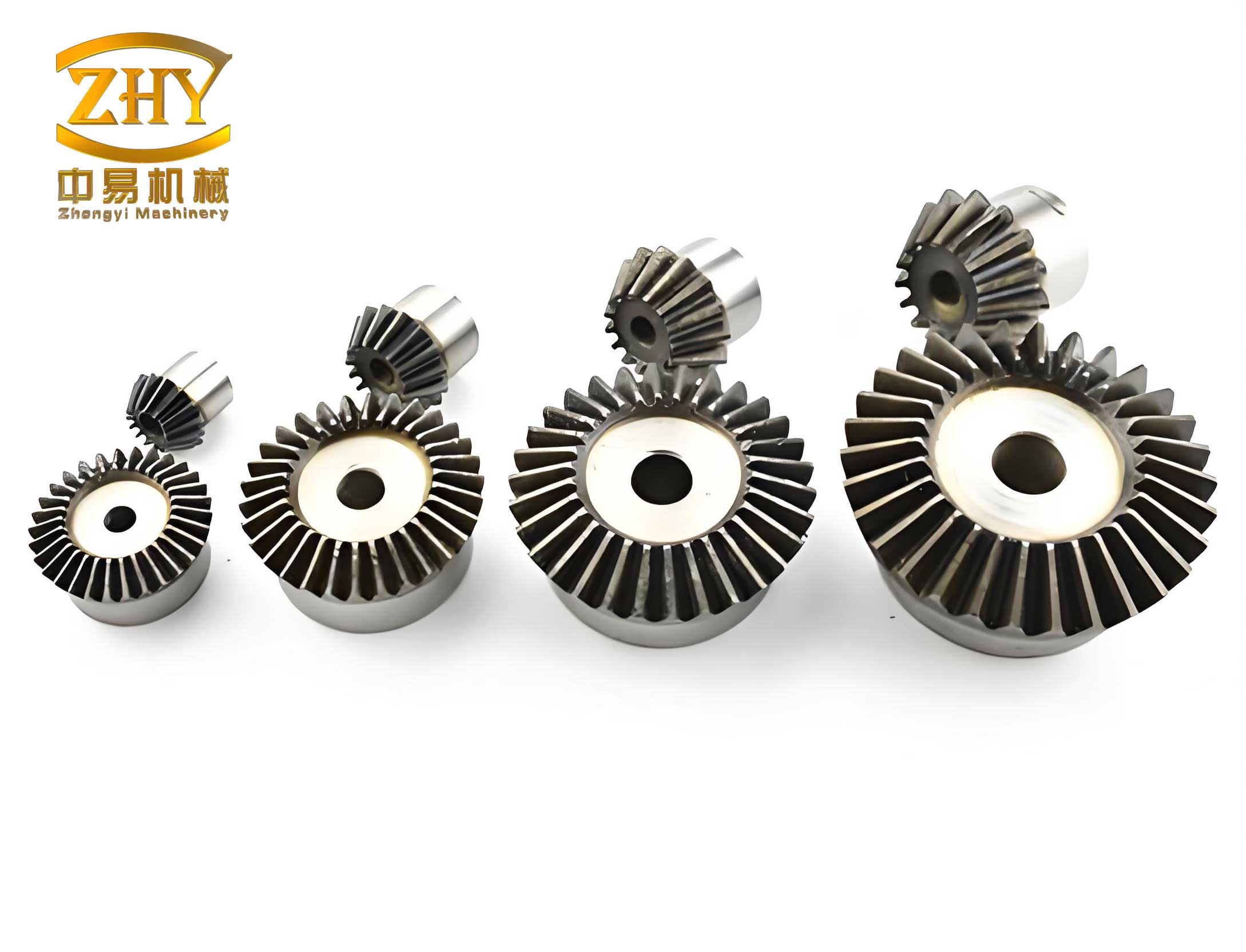
With the geometric parameters established, I proceeded to create three-dimensional models of the bevel gears using UG software. The modeling process involved extruding profiles based on the calculated dimensions, including tooth geometry defined by involute curves. The small and large bevel gears were individually modeled and then assembled in UG to form the complete transmission system. This assembly allows for visual verification of meshing and alignment, which is crucial for subsequent analysis. The three-dimensional model serves as a digital prototype, enabling detailed inspection of the bevel gear interaction without physical fabrication.
To ensure manufacturing accuracy, I selected a precision grade for the bevel gears based on GB 11365-89 standards, which specify tolerances for bevel and hypoid gears. A grade 6 precision was chosen, balancing cost and performance requirements. The main tolerances for the bevel gears are listed in the following table, covering aspects such as tooth thickness, pitch, and form errors.
| Tolerance Item | Driving Small Bevel Gear (mm) | Driven Large Bevel Gear (mm) |
|---|---|---|
| Tooth Thickness Upper Deviation | -0.018 | -0.027 |
| Tooth Thickness Lower Deviation | -0.050 | -0.069 |
| Tooth Thickness Tolerance | 0.032 | 0.042 |
| Total Helix Deviation | 0.038 | 0.053 |
| Pitch Cumulative Tolerance | 0.032 | 0.045 |
| Pitch Limit Deviation | 0.010 | 0.011 |
| Tooth Profile Relative Error Tolerance | 0.005 | 0.007 |
| Blank Tip Cone Line Runout Tolerance | 0.025 | 0.030 |
| Blank Reference Face Runout Tolerance | 0.025 | 0.012 |
| Blank Crown Distance Limit Deviation | -0.075 | -0.075 |
| Blank Tip Cone Angle Limit Deviation (°) | 0.8 | 0.8 |
Material selection is vital for the bevel gears’ performance under load. Both gears are made from 40Cr steel, a common alloy for high-strength applications. The mechanical properties of this material are provided in the table below, which includes density, elastic modulus, Poisson’s ratio, and strength values. These properties are essential inputs for finite element analysis, as they influence stress and deformation responses.
| Property | Value |
|---|---|
| Density (kg/m³) | 7820 |
| Elastic Modulus (GPa) | 211 |
| Poisson’s Ratio | 0.3 |
| Tensile Strength (MPa) | 1025 |
| Yield Strength (MPa) | 825 |
For the finite element modeling, I exported the three-dimensional assembly model from UG to ANSYS Workbench in a compatible format. The model was meshed using tetrahedral elements to capture the complex geometry of the bevel gears. The finite element mesh consisted of approximately 8.8 million elements and 12.4 million nodes, ensuring high resolution for contact analysis. The contact pairs between the bevel gears were defined with a friction coefficient of 0.08 and a contact factor of 0.85, which accounts for real-world surface interactions. The maximum penetration was set to 0.12 mm to simulate realistic deformation. Boundary conditions included applying a rotational speed of 4000 rpm to the driving bevel gear and a resisting torque of 80 Nm to the driven bevel gear. To study the effects of modification, I introduced profile modifications on both bevel gears: a modification of 0.0012 mm at the large end and 0.0008 mm at the small end. This modification aims to optimize load distribution and reduce edge stresses.
Theoretical contact stress calculations were performed using MATLAB, based on GB 10062-88 standards for bevel gear load capacity. The Hertzian contact stress formula for bevel gears can be expressed as: $$\sigma_H = Z_E \sqrt{\frac{F_t}{b \cdot d_1} \cdot \frac{u \pm 1}{u} \cdot K_A \cdot K_V \cdot K_{H\alpha} \cdot K_{H\beta}}$$ where \(\sigma_H\) is the contact stress, \(Z_E\) is the elasticity factor, \(F_t\) is the tangential load, \(b\) is the face width, \(d_1\) is the pitch diameter of the pinion, \(u\) is the gear ratio, and \(K\) factors account for application, dynamic, transverse load, and face load distribution. The results for contact stress before and after modification are summarized in the table below.
| Condition | Driving Bevel Gear Contact Stress (MPa) | Driven Bevel Gear Contact Stress (MPa) |
|---|---|---|
| Before Modification | 485.256 | 483.968 |
| After Modification | 480.187 | 478.945 |
The finite element simulation provided detailed insights into the equivalent stress distribution. Before modification, the maximum equivalent contact stress in the bevel gear system was concentrated in the meshing region, reaching 477.75 MPa. After modification, the maximum equivalent contact stress decreased to 474.48 MPa, a reduction of approximately 0.622%. This demonstrates that modification effectively lowers peak stresses, thereby improving the contact characteristics of the bevel gears. The stress reduction can be attributed to better load sharing across the tooth surfaces, minimizing localized high-stress zones. The von Mises stress contours from the simulation highlight how the stress is distributed, with the modified bevel gear showing a more uniform pattern.
Contact pattern analysis is crucial for assessing the performance of bevel gears. The contact斑点 (contact spots) indicate the areas where teeth come into contact under load. From the finite element results, the contact patterns before and after modification were compared. Before modification, the contact spots were relatively concentrated, with limited coverage along the tooth length and height. After modification, the contact spots expanded, covering a larger area both longitudinally and transversely. This expansion signifies improved contact conditions, as a larger contact area reduces pressure and wear. The contact pattern enhancement is a direct result of the profile modification, which adjusts the tooth geometry to promote even contact distribution.
To validate the accuracy of the methods, I compared the theoretical contact stress values with the finite element simulation results. The relative errors were calculated using the formula: $$\text{Relative Error} = \left| \frac{\sigma_{\text{theory}} – \sigma_{\text{FEM}}}{\sigma_{\text{theory}}} \right| \times 100\%$$ The comparison is presented in the table below, showing that the errors are within 2%, confirming the reliability of both numerical and simulation approaches.
| Comparison Item | Driving Bevel Gear | Driven Bevel Gear |
|---|---|---|
| Theoretical Contact Stress Before Modification (MPa) | 485.256 | 483.968 |
| FEM Equivalent Contact Stress Before Modification (MPa) | 477.45 | 477.45 |
| Relative Error Before Modification (%) | 1.609 | 1.347 |
| Theoretical Contact Stress After Modification (MPa) | 480.187 | 478.945 |
| FEM Equivalent Contact Stress After Modification (MPa) | 474.48 | 474.48 |
| Relative Error After Modification (%) | 1.188 | 0.932 |
In summary, this study underscores the importance of modification in enhancing the contact characteristics of bevel gears for mold applications. By integrating numerical computations with finite element simulations, I have shown that profile modification reduces maximum contact stress and enlarges contact spots, leading to better load distribution and potentially longer service life. The close agreement between theoretical and simulation results validates the methodology, providing a robust framework for optimizing bevel gear designs. Future work could explore different modification profiles or materials to further improve performance. Ultimately, understanding these aspects contributes to the development of more efficient and reliable mold systems, where bevel gears play a pivotal role in power transmission.
The analysis of bevel gears in this context also highlights broader implications for gear design. For instance, the contact stress equations used here can be adapted for other types of bevel gears, such as spiral or hypoid gears. Additionally, the finite element modeling techniques demonstrate how virtual prototyping can reduce development costs and time. As industries demand higher precision and durability, studies like this one offer valuable insights into achieving those goals through careful design and modification.
Furthermore, the role of bevel gears in mold systems cannot be overstated. These gears often operate under high loads and speeds, making their contact behavior a critical factor in overall system performance. By applying modification techniques, engineers can mitigate common issues like pitting and scoring, which are prevalent in heavily loaded bevel gears. The mathematical models developed here, including those for stress calculation and contact ratio, serve as tools for predictive maintenance and design optimization.
In conclusion, the research presented here provides a comprehensive approach to analyzing and improving bevel gears for mold applications. Through detailed parameter calculation, three-dimensional modeling, and advanced finite element analysis, I have demonstrated that modification is an effective strategy for enhancing contact characteristics. This work lays the groundwork for further investigations into bevel gear dynamics, noise reduction, and thermal effects, all of which are essential for advancing gear technology in industrial settings.