
The operational dynamics of gear transmission systems constitute a critical research domain within power transmission engineering, primarily driven by two interconnected concerns. Firstly, the vibration signature of a gear pair is the principal source of radiated noise. The dynamic forces generated at the meshing interface are transmitted through supporting bearings and the housing structure, manifesting as undesirable acoustic emissions. Secondly, and of equal importance, is the implication of these dynamic forces on the structural integrity and durability of the gears. Under high-speed conditions, the dynamic loads borne by the teeth can significantly exceed those predicted under quasi-static conditions, directly influencing bending and contact fatigue life. Therefore, a comprehensive understanding requires bridging the traditionally separate fields of gear noise/vibration analysis and gear strength/durability assessment.
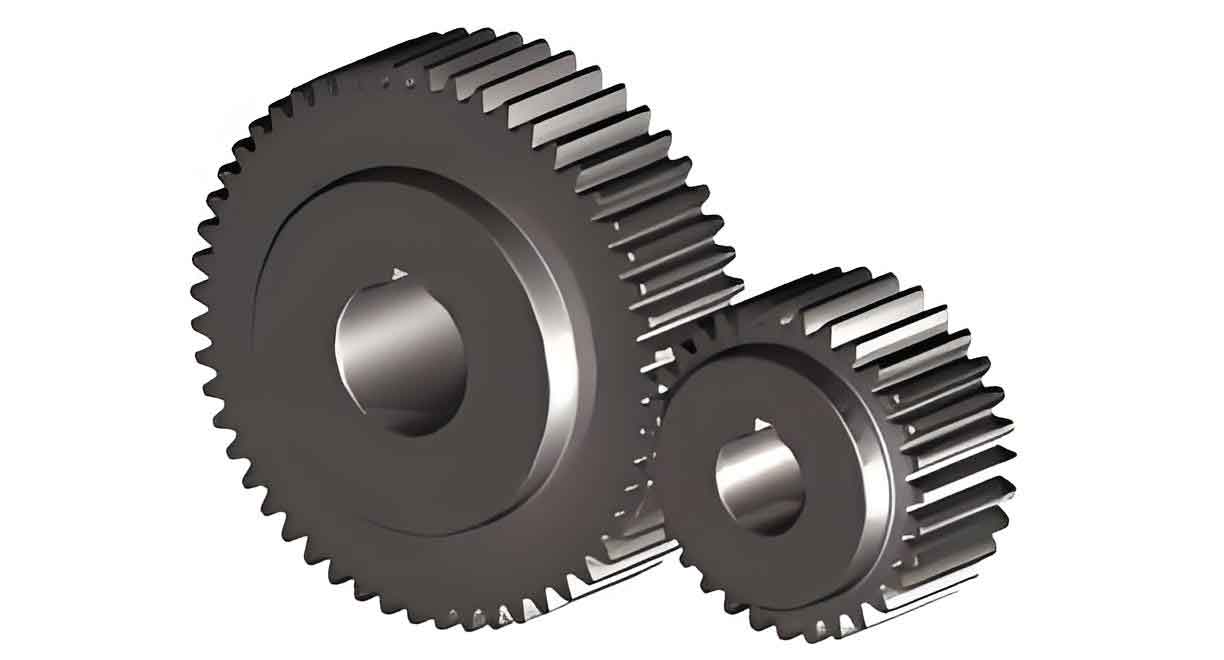
In vibration studies, the dynamic response of a gear pair is frequently characterized by its Dynamic Transmission Error (DTE). For a pair of spur gears, this is defined as the kinematic error along the line of action, representing the deviation from perfect conjugate motion. It can be expressed as:
$$ DTE(t) = r_{b1} \theta_1(t) + r_{b2} \theta_2(t) $$
where \( DTE(t) \) is the dynamic transmission error, \( r_{b1} \) and \( r_{b2} \) are the base circle radii of the driving and driven spur gears respectively, and \( \theta_1(t) \) and \( \theta_2(t) \) are the torsional vibratory displacements of the gears. The DTE is governed by the parametric excitation from time-varying mesh stiffness and any non-linearities such as backlash, making spur gears a classic example of a parametrically excited non-linear system.
Conversely, durability analysis focuses on the dynamic amplification of stress within the gear tooth, particularly at the root fillet where bending fatigue failure initiates. This is quantified using a Dynamic Factor (DF), defined as the ratio of the maximum dynamic root stress to the maximum static root stress under the same nominal load:
$$ DF = \frac{[\epsilon_{dyn}(t)]_{max}}{[\epsilon_{sta}(t)]_{max}} $$
Here, \( \epsilon_{dyn}(t) \) and \( \epsilon_{sta}(t) \) represent the time-history of root strain (a direct indicator of stress) under dynamic and static (or very low-speed) conditions, respectively.
Historically, research efforts have often proceeded in parallel, with dynamic models predicting DTE for noise assessment and separate experimental or numerical studies estimating DF for durability. The core hypothesis driving this work is that these two metrics, DTE and DF, are fundamentally linked through the dynamic meshing force. A larger vibratory response (high DTE amplitude) should inherently generate higher dynamic tooth loads, leading to a larger DF. However, comprehensive experimental data simultaneously capturing both DTE and DF from the same pair of spur gears under identical operating conditions has been limited. This study aims to fill that gap. The objectives are threefold: (1) to describe an integrated experimental methodology for the simultaneous high-fidelity measurement of DTE and root strain (for DF) in spur gears; (2) to present a comprehensive set of experimental data for both unmodified and modified spur gear pairs across a wide range of speeds and loads, capturing non-linear dynamic phenomena; and (3) to demonstrate and quantify the empirical relationship between the measured DTE and DF values.
Experimental Apparatus and Methodology for Spur Gear Testing
The experimental investigation was conducted using a power-circulating (back-to-back or four-square) gear test rig, a standard configuration for applying high torques without requiring a prime mover of equivalent power. The schematic and operational principle are detailed below.
1.1 Test Rig Configuration
The central component is a rigid test gearbox housing the spur gear pair under investigation. An identical reaction gearbox, with a gear pair of the same specifications, is connected in series via two shafts, forming a closed mechanical power loop. Torque is introduced into this loop by manually twisting the shafts relative to each other and locking them with a torque clutch. This preloads both gear meshes with the same nominal static torque. A DC motor is connected to one of the shafts to overcome frictional losses and drive the system at the desired rotational speed. Large inertia flywheels and flexible couplings are installed on the connecting shafts to dynamically isolate the test gearbox from the reaction gearbox and motor, ensuring that the dynamic phenomena measured are predominantly generated by the test spur gear pair.
The test rig is designed for high-speed and high-load operation, capable of testing spur gears at speeds up to 4000 rpm and static torques up to 500 N·m. The gears are generously lubricated via jet oil sprays directed at the meshing zone and bearings to minimize friction and damping. The test gears are mounted on shafts supported by large-diameter, preloaded bearings to constrain lateral shaft motions, ensuring that the dominant vibration modes are torsional.
1.2 Integrated Measurement Systems
A unique aspect of this setup is the integration of two synchronous measurement systems: one for dynamic root strain and one for DTE.
Dynamic Strain Measurement for Dynamic Factor (DF): The root fillet strain on the tension side of a tooth is measured using miniature foil strain gauges. The gauges are precisely positioned at the center of the tooth face width, aligned with the center of the root fillet curvature. For each test spur gear, a full Wheatstone bridge configuration is completed using gauges installed on multiple teeth around the circumference. This configuration compensates for temperature effects and minimizes noise. The signals from the rotating bridge are transmitted via a high-quality slip-ring unit to a signal conditioner and amplifier. The conditioned strain signal \( \epsilon(t) \) is then acquired at a high sampling rate (100 kHz). The Dynamic Factor is calculated according to its definition. A very low speed (200 rpm) run is used to capture the quasi-static strain waveform \( \epsilon_{sta}(t) \). At each test speed \( N \), the dynamic strain waveform \( \epsilon_{dyn}(t, N) \) is recorded. The DF at speed \( N \) is then:
$$ DF(N) = \frac{\max(|\epsilon_{dyn}(t, N)|)}{\max(|\epsilon_{sta}(t)|)} $$
Dynamic Transmission Error (DTE) Measurement: The DTE is measured using an accelerometer-based technique. Two miniature, high-sensitivity accelerometers are mounted on a rigid flange attached to each gear shaft, diametrically opposite each other at the same radial distance \( r_a \) from the center. For a given spur gear \( j \), the tangential acceleration signals are:
$$ a_1^j(t) = r_a \ddot{\theta}_j(t) + g \sin(\Omega_j t + \phi) $$
$$ a_2^j(t) = r_a \ddot{\theta}_j(t) + g \sin(\Omega_j t + \phi + \pi) $$
where \( \ddot{\theta}_j(t) \) is the angular acceleration of the gear, \( g \) is gravitational acceleration, and \( \Omega_j \) is the rotational speed. Summing the two signals cancels the gravitational component, yielding a clean measurement of angular acceleration:
$$ \ddot{\theta}_j(t) = \frac{a_1^j(t) + a_2^j(t)}{2 r_a} $$
The angular accelerations for both spur gears are then double-integrated in the frequency domain (with appropriate high-pass filtering to mitigate drift) to obtain the vibratory angular displacements \( \theta_1(t) \) and \( \theta_2(t) \). The DTE is finally computed as:
$$ DTE(t) = r_{b1} \theta_1(t) + r_{b2} \theta_2(t) $$
For analysis, the root-mean-square (RMS) value of the DTE time signal, \( DTE_{RMS} \), is often used as a scalar metric for vibration amplitude. Both acceleration and strain signals are transmitted via the multi-channel slip-ring assembly, conditioned, and synchronously sampled by a high-speed data acquisition system controlled by LabVIEW software.
1.3 Test Specimens and Procedure
Two distinct pairs of spur gears were investigated to understand the effect of tooth micro-geometry. Both pairs share the same fundamental macro-geometric parameters, detailed in Table 1.
| Parameter | Symbol | Value |
|---|---|---|
| Number of Teeth | z | 50 |
| Module | m_n | 3.00 mm |
| Pressure Angle | α | 20° |
| Center Distance | a | 150.00 mm |
| Base Circle Radius | r_b | 140.95 mm |
| Operating Pitch Circle Radius | r’ | 150.00 mm |
| Face Width | F | 20.00 mm |
| Theoretical Contact Ratio | ε_α | ~1.8 |
The first pair, termed “unmodified,” features standard involute profiles. The second pair, termed “modified,” incorporates tip relief to reduce transmission error excitation and mitigate meshing impacts. Tests were conducted at three static torque levels: T = 100, 200, and 300 N·m. For each torque, the speed was varied from 200 rpm to 4000 rpm (and back down) in fine increments. Data was acquired at steady-state conditions at each speed point. This “sweep-up” and “sweep-down” procedure is essential for capturing hysteretic non-linear behaviors like jump phenomena associated with tooth separation.
Experimental Results: Dynamic Response of Spur Gears
The following sections present the experimental results for the dynamic factor and dynamic transmission error, highlighting the non-linear dynamic behavior of the tested spur gears.
2.1 Dynamic Factor (DF) Response
The measured Dynamic Factor for the unmodified spur gears across the meshing frequency range is plotted in Figure X (Note: Data plots are described as Figure X, Y, Z for structural flow, representing the original figures 6-9). The results show a clear and strong non-linear response.
- Resonance Peaks: Distinct resonance peaks are observable. The primary resonance occurs when the meshing frequency \( f_m \) coincides with the system’s natural frequency \( f_n \). For the unmodified gears at T=200 N·m, \( f_n \) is approximately 2800 Hz. Sub-harmonic resonances are also evident at \( f_m ≈ f_n/2 \) and \( f_m ≈ f_n/3 \).
- Non-Linear Jump Phenomena: Around the primary resonance peak, a classic “jump” discontinuity is visible, indicative of strong non-linearity from periodic tooth contact loss. The DF value on the sweep-up branch is different from that on the sweep-down branch, forming a hysteresis loop. At T=200 N·m, the peak DF reaches about 1.8 during sweep-up but jumps to 2.4 during sweep-down.
- Effect of Load (Torque): Increasing the static torque shifts the resonance peaks to slightly higher frequencies. This is attributed to the load-dependent meshing stiffness; higher torque increases the average number of teeth in contact and the contact zone, effectively stiffening the gear mesh and raising \( f_n \). The magnitude of the DF peak also changes with load, demonstrating the complex interaction between static load and dynamic amplification in spur gears.
The results for the modified spur gears are presented in Figure Y. While the overall pattern of resonance and non-linear jumps remains, the severity is reduced. For instance, at T=200 N·m, the maximum DF value for the modified pair is around 2.0, compared to 2.4 for the unmodified pair. This confirms that profile modification is an effective measure for reducing dynamic tooth loads in spur gears, primarily by smoothing the mesh stiffness variation and reducing impact severity.
2.2 Dynamic Transmission Error (DTE) Response
The RMS values of the simultaneously measured DTE for the unmodified spur gears are shown in Figure Z. The DTE response mirrors the DF response remarkably well. The same resonance peaks and non-linear jump phenomena are clearly present in the DTE data. The amplitude of \( DTE_{RMS} \) for the unmodified gears is significantly higher than that for the modified gears (Figure W), paralleling the trend observed in the DF data. This visual correlation strongly suggests a fundamental link between the kinematic vibratory response (DTE) and the resulting dynamic stress (DF).
A summary of key response metrics at resonance for both gear types is provided in Table 2.
| Gear Type | Sweep Direction | Approx. Resonant Freq. (Hz) | Peak DF | Peak DTE_RMS (μm) |
|---|---|---|---|---|
| Unmodified Spur Gears | Up | 2800 | 1.80 | ~10 |
| Down | 2750 | 2.40 | ~18 | |
| Modified Spur Gears | Up | 2850 | 1.65 | ~5 |
| Down | 2800 | 2.00 | ~8 |
Establishing the Correlation Between DTE and DF for Spur Gears
The core finding of this experimental study is the quantitative relationship between the dynamic transmission error and the dynamic stress factor. By plotting the \( DTE_{RMS} \) values against their corresponding DF values for all tested speeds and both sweep directions—effectively creating a scatter plot—a clear trend emerges. This is illustrated in Figure V for data at T=200 N·m and T=300 N·m.
The data points cluster around a straight line. Physically, when DF = 1, the system is in a quasi-static state, and the vibratory component of DTE should be zero (ignoring static transmission error). Therefore, the relationship can be modeled as a linear function passing through the point (DF=1, DTE_RMS=0):
$$ (DTE_{RMS}) = \beta \cdot (DF – 1) $$
The parameter \( \beta \) (in micrometers) represents the slope of the correlation and can be interpreted as the incremental vibratory displacement per unit increase in dynamic load factor. Its value depends on the gear geometry, modification, and applied load. Linear regression on the experimental data yields the following values for \( \beta \):
| Spur Gear Type | Torque T (N·m) | Correlation Slope β (μm) |
|---|---|---|
| Unmodified | 200 | 12.3 |
| Unmodified | 300 | 13.1 |
| Modified | 200 | 7.8 |
| Modified | 300 | 11.8 |
The results show that \( \beta \) is generally smaller for the modified spur gears, indicating that for the same increase in DF, the associated vibration amplitude (DTE) is lower. This is consistent with the role of modifications in improving meshing smoothness. The increase in \( \beta \) with torque for both gear types suggests that the relationship may have a slight non-linearity or that the system’s effective stiffness changes with load, affecting the conversion between force (related to DF) and displacement (DTE).
Conclusion
This investigation has successfully demonstrated an integrated experimental approach for the simultaneous study of vibration and durability dynamics in spur gears. A specialized test rig equipped with synchronized root strain and accelerometer-based DTE measurement systems was employed to collect comprehensive data from both unmodified and profile-modified spur gear pairs under various loads and speeds.
The key experimental findings are:
- Both the Dynamic Factor (DF) and the Dynamic Transmission Error (DTE) for spur gears exhibit pronounced non-linear behavior, including primary resonance, sub-harmonic resonances, and hysteretic jump phenomena due to tooth contact loss.
- Profile modification effectively reduces the amplitude of both DF and DTE responses, confirming its dual benefit in lowering dynamic loads (improving durability) and reducing vibration (lowering noise).
- Most significantly, a strong, quantifiable linear correlation exists between the RMS value of the dynamic transmission error and the dynamic factor. The relationship is expressed as \( DTE_{RMS} = \beta (DF – 1) \), where the slope \( \beta \) is a characteristic parameter influenced by gear design and load.
This empirical correlation provides a crucial bridge between the fields of gear dynamics and gear strength analysis. It implies that for a given pair of spur gears, measuring the kinematic vibration (DTE) can allow for an estimation of the dynamic stress amplification (DF), and vice-versa. This linkage can significantly enhance predictive models, design validation processes, and condition monitoring strategies for spur gear transmissions, leading to more reliable, quiet, and durable mechanical systems.