
As a researcher in the field of mechanical engineering, I have dedicated significant efforts to exploring advanced gear cutting techniques that enhance the performance and efficiency of cylindrical gears. Gears are fundamental components in machinery, and with industrial development, the demand for high-performance transmissions has grown exponentially. In this context, cylindrical gears with circular arc tooth lines, often abbreviated as CCT gears, have emerged as a promising alternative due to their superior characteristics such as increased load capacity, reduced noise, and smooth operation. This article delves into the gear cutting principles, experimental studies, and equipment design associated with these gears, aiming to provide a comprehensive overview of their potential applications.
The gear cutting process for CCT gears is rooted in the concept of simulating a virtual rack with concave and convex tooth surfaces formed by parts of imaginary cones. The central section of this rack features a straight-line tooth profile, ensuring that the mating gear maintains an involute shape in that section, while other parallel sections exhibit conjugate tooth profiles approximating involutes. The gear cutting is achieved using a cutter with straight blades that generate the tooth surfaces during rotation. Over the years, various gear cutting methods have been developed, each with its own advantages and limitations.
One common gear cutting approach is the ordinary milling method, which can be adapted on standard vertical or horizontal milling machines. In this gear cutting technique, an end-mounted cutter with straight blades—comprising outer and inner blades—is used to separately cut the concave and convex tooth surfaces through a generating motion. After each cut, the workpiece is retracted and indexed. This gear cutting method, while suitable for small-scale production, is inefficient due to its discontinuous nature. For instance, a Japanese manufacturer developed a dedicated machine based on this gear cutting principle, but its productivity remains low. The gear cutting process can be mathematically described by the following parameters: let the module be $m$, the number of teeth be $z$, and the generating radius be $R_g$. The tooth line curvature is defined by an arc of radius $R_c$, and the relationship between these parameters influences the gear cutting accuracy. The equation for the circular arc tooth line in parametric form is: $$x = R_c \cos(\theta), \quad y = R_c \sin(\theta),$$ where $\theta$ is the angular parameter along the tooth width. This simplicity in geometry facilitates gear cutting but requires precise control.
To improve efficiency, continuous milling methods have been investigated. In this gear cutting strategy, the cutter teeth are arranged along an Archimedes spiral with a pitch equal to the gear’s circular pitch, enabling continuous indexing during gear cutting. This gear cutting approach, studied by institutions like Moscow Aviation Institute, produces tooth lines that are parts of extended cycloids. A Swiss company has even designed and built machines based on this continuous gear cutting principle, showcasing higher throughput. The gear cutting dynamics can be expressed using the formula for the spiral: $$r = a + b\phi,$$ where $r$ is the radial distance, $\phi$ is the angle, and $a$ and $b$ are constants related to the gear cutting parameters. However, this gear cutting method still faces challenges in terms of tool interference and complexity.
Another innovative gear cutting technique is the circular broaching method, which I have extensively researched. This gear cutting process involves a circular broach cutter divided into four zones: two cutting zones for concave and convex surfaces, separated by indexing zones. The cutter rotates continuously while the workpiece undergoes a combined rotational and translational motion to simulate pure rolling along the rack’s pitch plane. This gear cutting method allows for high-efficiency production of CCT gears, as it integrates generating cutting, tip relief, and root forming in a single operation. The gear cutting time per tooth slot can be as low as a few seconds, making it suitable for medium-module gears. The key gear cutting parameters are summarized in Table 1, which highlights the relationship between module range, cutter diameter, and cutting speed.
| Module Range (mm) | Cutter Diameter (mm) | Generating Radius (mm) | Cutting Speed (m/min) | Number of Cutter Teeth | Cutting Time per Slot (s) |
|---|---|---|---|---|---|
| 2-4 | 200-300 | 100-150 | 60-100 | 40-60 | 2-4 |
| 4-6 | 300-400 | 150-200 | 50-80 | 50-70 | 3-5 |
| 6-8 | 400-500 | 200-250 | 40-70 | 60-80 | 4-6 |
The gear cutting efficiency is further enhanced by the ability to machine two workpieces simultaneously in a dual-station setup. The mathematical model for the gear cutting motion involves the workpiece rotation angle $\omega$ and translation velocity $v$, which must satisfy the condition for pure rolling: $$v = R_p \omega,$$ where $R_p$ is the pitch radius. This gear cutting principle ensures accurate tooth generation while minimizing idle time.
In addition to these gear cutting methods, other approaches like form cutting followed by rolling, and grinding have been explored. For example, a Japanese university developed a gear cutting process using a double-sided cutter for roughing and a finished rolling die for finishing, achieving high precision. Grinding methods, which replace the milling cutter with a cup-shaped grinding wheel, offer precision gear cutting for hardened gears. However, these gear cutting techniques often involve higher costs and complexity, limiting their widespread adoption.
To validate the performance of CCT gears produced through advanced gear cutting, I conducted a series of experimental studies. The first focused on bending fatigue strength, using a self-designed testing rig for medium-module gears. Three different CCT gear sets were compared with standard involute spur gears under controlled conditions. The load application point was set at the highest point of single-tooth contact, with a maximum load of $P_{max} = 5000$ N and a reduced load of $P_{min} = 2500$ N in a sinusoidal waveform. The results, summarized in Table 2, show that CCT gears exhibit significantly higher median fatigue life $N_{50}$, especially as the width-to-diameter ratio $b/d$ increases. This underscores the advantage of gear cutting processes that optimize tooth geometry.
| Gear Type | Module (mm) | Width-to-Diameter Ratio $b/d$ | Median Fatigue Life $N_{50}$ (cycles) | Improvement Factor |
|---|---|---|---|---|
| Spur Gear | 4 | 0.5 | 1.2 × 10^6 | 1.0 |
| CCT Gear | 4 | 0.5 | 2.5 × 10^6 | 2.1 |
| CCT Gear | 4 | 0.7 | 3.8 × 10^6 | 3.2 |
| CCT Gear | 4 | 0.9 | 5.0 × 10^6 | 4.2 |
The gear cutting process directly influences these outcomes, as precise tooth profiles reduce stress concentrations. The bending stress $\sigma_b$ can be estimated using the Lewis formula: $$\sigma_b = \frac{W_t}{m b Y},$$ where $W_t$ is the tangential load, $m$ is the module, $b$ is the face width, and $Y$ is the Lewis form factor. For CCT gears, $Y$ tends to be higher due to the curved tooth line, enhancing strength when proper gear cutting is employed.
Noise and contact pattern tests were also performed on a gear noise testing machine. Despite the CCT gears having a lower accuracy grade (approximately AGMA 9) compared to the spur gears (AGMA 7), they demonstrated a noise reduction of 3-5 dB across various rotational speeds. This highlights how gear cutting techniques that produce smooth tooth surfaces contribute to quieter operation. The contact patterns remained stable within the allowable center distance variation of $\Delta a = \pm 0.1$ mm, meeting precision standards. The sound pressure level $L_p$ in decibels can be related to gear cutting quality by the empirical formula: $$L_p = 20 \log_{10}\left(\frac{v}{v_0}\right) + K,$$ where $v$ is the sliding velocity, $v_0$ is a reference velocity, and $K$ is a constant dependent on gear cutting parameters.
Further practical validation involved gear cutting and field testing of CCT gears for a tractor final drive application. The original spur gears were replaced with CCT gears machined using an adapted milling machine with a small-diameter cutter based on ordinary gear cutting principles. The gears, with parameters like module $m=5$ mm and 40 teeth, were installed in three tractors and operated for over 2000 hours. Post-operation inspection revealed excellent contact patterns covering nearly 90% of the tooth surface, with no interference or binding. This contrasts with the original spur gears, which showed only 60% contact due to misalignment issues. The gear cutting process here, though basic, proved effective for medium-precision applications, and the noise reduction was perceptible to operators.
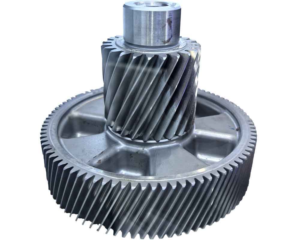
The success of these gear cutting endeavors hinges on the design of specialized equipment. For the circular broaching gear cutting method, I developed a circular broach cutter and a dedicated machine. The cutter features a body with radial slots for inserting blade segments, which can be adjusted radially and axially via set screws to accommodate different modules while maintaining the generating radius $R_g$. This flexibility is crucial for versatile gear cutting. The cutter design ensures that each blade sequentially performs tip relief, generating cutting, and root forming, all integral to efficient gear cutting.
The gear cutting machine’s transmission system includes a main spindle driven by a motor through a belt and gear reduction, with a cam mechanism controlling the linear reciprocation of the workpiece saddle. During gear cutting, the workpiece rotates and translates via a gear rack and pinion system, synchronized with the cutter rotation through change gears. The indexing is achieved using a precision hydraulic cylinder and a face tooth coupling, allowing quick and accurate division. The kinematic chain for gear cutting can be modeled as: $$\omega_w = \frac{v_t}{R_p},$$ where $\omega_w$ is the workpiece angular velocity and $v_t$ is the translational velocity. This gear cutting machine enables high-productivity manufacturing, with the potential for dual-station operation to further boost output.
In terms of gear cutting tool materials, the choice depends on the workpiece hardness and desired efficiency. For CCT gears, which often involve medium-carbon steels, coated carbide tools are recommended due to their wear resistance. The tool life $T$ in gear cutting can be expressed by Taylor’s tool life equation: $$VT^n = C,$$ where $V$ is the cutting speed, $n$ is an exponent, and $C$ is a constant. Optimizing these parameters is essential for cost-effective gear cutting.
To summarize, the gear cutting methods for cylindrical gears with circular arc tooth lines offer significant benefits in performance and manufacturing efficiency. Through my research, I have demonstrated that gear cutting techniques like circular broaching can achieve high productivity while maintaining quality. The experimental studies confirm that CCT gears exhibit superior bending fatigue life and noise reduction compared to traditional spur gears, validating the importance of advanced gear cutting processes. However, challenges remain, such as the limited applicability due to axial constraints similar to herringbone gears, and the need for further refinement in gear cutting accuracy for mass production.
Future work should focus on optimizing gear cutting parameters using computational models, exploring dry gear cutting to reduce environmental impact, and integrating adaptive control in gear cutting machines. The formula for overall gear cutting efficiency $\eta$ can be defined as: $$\eta = \frac{\text{Useful cutting time}}{\text{Total cycle time}} \times 100\%.$$ By improving this through innovative gear cutting strategies, the adoption of CCT gears could expand in industries such as automotive, aerospace, and heavy machinery.
In conclusion, gear cutting is a pivotal aspect of gear manufacturing, and the development of methods for CCT gears represents a step forward in transmission technology. My research underscores the potential of these gears and the gear cutting processes that enable their production, paving the way for more reliable and efficient mechanical systems. As gear cutting continues to evolve, it will undoubtedly contribute to meeting the growing demands for high-performance gears in modern engineering applications.