
In the design of herringbone gears, it is essential to reserve a sufficient relief groove width to allow the hob to complete the cutting process without interference. The standard Q/ZB 135-73 provides the minimum relief groove width \( b_{\min} \) for hobbing herringbone gears. However, that table assigns the same value regardless of the number of teeth on the larger gear. In practice, different numbers of teeth on the larger gear can lead to different minimum relief groove widths for herringbone gears. In this work, we present a computational model to determine the minimum relief groove width for herringbone gears based on the module \( m_n \), helix angle \( \beta \), and the number of teeth \( Z \) on the larger gear. We have performed extensive numerical calculations and generated tables that allow designers to quickly look up the required \( b_{\min} \) values for herringbone gears. These tables are far more convenient and accurate than the single-value standard.
Mathematical Model and Calculation Procedure
We simplify the hob and the herringbone gear to establish a geometric model, as shown in the schematic figure. The coordinate system is defined as follows: the gear axis is taken as the \( z \)-axis, the two perpendicular centerlines on the end face \( N \) of the relief groove are the \( x \)-axis and \( y \)-axis. The hob axis intersects the \( x \)-axis perpendicularly and makes an angle \( \gamma \) with the \( z \)-axis, where \( \gamma = 90^\circ – (\lambda + \beta) \), with \( \lambda \) being the hob’s cutting edge inclination and \( \beta \) the helix angle of the herringbone gear. Consequently, the angle between the hob axis and the \( y \)-axis is \( \gamma \) as well.
Let \( D_1 \) be the gear root circle diameter, \( D_2 \) the gear tip circle diameter, \( D \) the hob tip circle diameter, and \( L \) the hob length. The hob’s cylindrical outer surface is tangent to the gear root cylinder at point \( P \), which lies on the plane \( M_3 \) (the mid-plane of the hob) on the gear tip circle, and on the plane \( N \) (the end face of the relief groove) on the gear root circle. At this geometry, the distance between the hob axis and the gear axis is \( x_0 = (D_1 + D)/2 \).
Two scenarios are considered. In the first scenario, when the hob length is relatively short, the outer circle of the hob end face \( M_1 \) intersects the gear tip cylinder at two points. In the second scenario, when the hob length is appropriate or long, there is only one intersection or no intersection at all. For both cases we only consider the first octant.
First scenario: The hob end face \( M_1 \) passes through the point \( (x_0, L\cos\gamma, L\sin\gamma) \) and its normal vector is \( \mathbf{n} = (0, \cos\gamma, \sin\gamma) \). The equation of this end face is:
\[
\cos\gamma (y – L\cos\gamma) + \sin\gamma (z – L\sin\gamma) = 0 \tag{1}
\]
The hob outer cylindrical surface equation is:
\[
(x – x_0)^2 + (-y\sin\gamma + z\cos\gamma)^2 = D^2/4 \tag{2}
\]
The gear tip cylindrical surface equation is:
\[
x^2 + y^2 = D_2^2/4 \tag{3}
\]
We introduce a parameter \( t \) and consider only the first octant. Let:
\[
x = \frac{D_2}{2} t \quad,\quad y = \frac{D_2}{2} \sqrt{1 – t^2} \tag{4}
\]
Substituting into (1) gives the \( z \)-coordinate:
\[
z = \frac{L}{\sin\gamma} – \frac{D_2 \sqrt{1 – t^2}}{2 \tan\gamma} \tag{5}
\]
Then substitute (4) and (5) into (2) and rearrange to obtain:
\[
C_1 t^2 + C_2 t + C_3 = C_4 \sqrt{1 – t^2} \tag{6}
\]
where the coefficients are:
\[
\begin{aligned}
C_1 &= -\frac{D_2 \cos\gamma}{4L}, \\
C_2 &= -\frac{x_0 \tan\gamma \sin\gamma}{L} = -\frac{(D_1 + D) \sin\gamma}{2L}, \\
C_3 &= \frac{(D_1^2 + 2D D_1 + D^2/4 + L^2/\tan^2\gamma + D_1^2/(4\sin^2\gamma)) \sin\gamma}{D_2 L}
\end{aligned}
\]
Squaring both sides of (6) leads to a quartic equation in \( t \):
\[
e_4 t^4 + e_3 t^3 + e_2 t^2 + e_1 t + e_0 = 0 \tag{7}
\]
where:
\[
e_4 = C_1^2,\quad e_3 = 2C_1 C_2,\quad e_2 = C_2^2 + 2C_1 C_3 + 1,\quad e_1 = 2C_2 C_3,\quad e_0 = C_3^2 – 1.
\]
Solving (7) for \( t \) and then substituting into (5) yields two possible \( z \) values; the larger one is the minimum relief groove width \( b_{\min} \) for this scenario.
Second scenario: When the hob end face outer circle has either one or no intersection with the gear tip cylinder, we use a different approach. Substituting (4) into (2) and solving for \( z \) (taking the positive branch):
\[
z(t) = \frac{D_2 \tan\gamma}{2} \sqrt{1 – t^2} + \sqrt{\frac{D^2}{4} – \frac{(D_2 t/2 – x_0)^2}{\cos^2\gamma}} \tag{8}
\]
To maximize \( z \) with respect to \( t \), we set the derivative \( dz/dt = 0 \):
\[
\frac{dz}{dt} = -\frac{D_2 \tan\gamma\, t}{2\sqrt{1 – t^2}} – \frac{D_2 (D_2 t/2 – x_0)}{2\cos\gamma \sqrt{D^2/4 – (D_2 t/2 – x_0)^2/\cos^2\gamma}} = 0
\]
This simplifies to a quartic equation in \( t \):
\[
A_4 t^4 + A_3 t^3 + A_2 t^2 + A_1 t + A_0 = 0 \tag{9}
\]
with coefficients:
\[
\begin{aligned}
A_4 &= \frac{D_1^2 \cos^2\gamma}{4}, \\
A_3 &= -D_2 x_0 \cos^2\gamma, \\
A_2 &= \frac{D^2 \sin^2\gamma}{4} – \frac{D_2^2}{4} + x_0^2 \cos^2\gamma, \\
A_1 &= D_2 x_0, \\
A_0 &= -x_0^2.
\end{aligned}
\]
Solving (9) gives the parameter \( t \) that maximizes \( z \). Substituting this \( t \) into (8) yields \( z_{\max} \), which is the \( b_{\min} \) for the second scenario. The final \( b_{\min} \) for the herringbone gear is taken as the larger value from the two scenarios.
Influence of the Modification Coefficient
The root diameter and tip diameter of the herringbone gear including the modification coefficient \( x_n \) are:
\[
\begin{aligned}
D_1 &= m_n \left( \frac{Z}{\cos\beta} – 2h_a^* – 2c^* + 2x_n \right) \\
D_2 &= m_n \left( \frac{Z}{\cos\beta} + 2h_a^* + 2x_n \right)
\end{aligned}
\]
The distance \( x_0 = (D_1 + D)/2 \) also depends on \( x_n \). For typical values of \( x_n \) (e.g., 0, 0.1, 0.2), the resulting changes in \( b_{\min} \) are negligible compared to the influence of the number of teeth \( Z \). Our numerical checks confirmed that for \( x_n = 0, 0.1, 0.2 \) the computed \( b_{\min} \) values differ only by a few hundredths of a millimeter, which is practically insignificant. Therefore, the modification coefficient can be ignored when looking up the relief groove width for herringbone gears.
Numerical Results and Tables
Using the above model, we programmed a computer code to compute the minimum relief groove width for herringbone gears under various combinations of module \( m_n \), helix angle \( \beta \), and number of teeth \( Z \). The results are organized into two tables: one for “Type I” (corresponding to AA-grade herringbone gears) and one for “Type II” (corresponding to A, B, C-grade herringbone gears). The module ranges from 4 to 10, the helix angle from 30° to 40°, and the number of teeth from 40 to 120. The following tables present the computed \( b_{\min} \) values in millimeters.
| \( \beta \) | \( Z \) | Module \( m_n \) (mm) | ||||||
|---|---|---|---|---|---|---|---|---|
| 4 | 5 | 6 | 7 | 8 | 9 | 10 | ||
| 30° | 40 | 45 | 55 | 64 | 68 | 78 | 88 | 99 |
| 60 | 46 | 56 | 65 | 69 | 79 | 89 | 100 | |
| 80 | 47 | 57 | 66 | 70 | 80 | 90 | 101 | |
| 100 | 47 | 58 | 67 | 71 | 81 | 91 | 102 | |
| 120 | 48 | 58 | 68 | 71 | 82 | 92 | 102 | |
| 35° | 40 | 45 | 55 | 64 | 68 | 78 | 89 | 99 |
| 60 | 49 | 59 | 66 | 70 | 80 | 90 | 100 | |
| 80 | 50 | 60 | 68 | 71 | 81 | 91 | 102 | |
| 100 | 51 | 61 | 69 | 71 | 81 | 92 | 102 | |
| 120 | 51 | 61 | 69 | 71 | 82 | 92 | 102 | |
| 40° | 40 | 51 | 61 | 70 | 73 | 83 | 94 | 107 |
| 60 | 53 | 63 | 71 | 74 | 84 | 95 | 107 | |
| 80 | 53 | 64 | 71 | 74 | 85 | 96 | 108 | |
| 100 | 54 | 64 | 72 | 74 | 85 | 96 | 108 | |
| 120 | 54 | 64 | 72 | 74 | 85 | 96 | 108 | |
| \( \beta \) | \( Z \) | Module \( m_n \) (mm) | ||||||
|---|---|---|---|---|---|---|---|---|
| 4 | 5 | 6 | 7 | 8 | 9 | 10 | ||
| 30° | 40 | 37 | 45 | 50 | 55 | 63 | 71 | 78 |
| 60 | 36 | 43 | 47 | 53 | 59 | 66 | 72 | |
| 80 | 38 | 44 | 48 | 54 | 60 | 67 | 73 | |
| 100 | 38 | 44 | 49 | 54 | 60 | 67 | 73 | |
| 120 | 39 | 45 | 49 | 55 | 60 | 68 | 74 | |
| 35° | 40 | 38 | 45 | 50 | 56 | 62 | 69 | 75 |
| 60 | 43 | 50 | 54 | 60 | 66 | 75 | 81 | |
| 80 | 41 | 47 | 51 | 58 | 64 | 71 | 77 | |
| 100 | 41 | 47 | 52 | 58 | 64 | 72 | 78 | |
| 120 | 41 | 48 | 52 | 58 | 64 | 72 | 78 | |
| 40° | 40 | 45 | 51 | 56 | 62 | 69 | 77 | 84 |
| 60 | 45 | 52 | 56 | 63 | 69 | 78 | 84 | |
| 80 | 45 | 52 | 56 | 63 | 69 | 78 | 84 | |
| 100 | 46 | 52 | 57 | 63 | 69 | 78 | 84 | |
| 120 | 46 | 52 | 57 | 63 | 70 | 78 | 84 | |
The values given above are the minimum relief groove widths for herringbone gears in millimeters. The Type I table applies to AA-grade herringbone gears, while the Type II table applies to A, B, and C grades. The tables cover modules from 4 to 10, helix angles 30°, 35°, and 40°, and tooth numbers from 40 to 120. For intermediate values, linear interpolation may be used.
Discussion of Results
From the tables we observe a clear trend: for a fixed module and helix angle, the required \( b_{\min} \) increases slightly as the number of teeth increases, but the increase is modest beyond a certain point (e.g., above 80 teeth). The influence of the helix angle is also noticeable: a larger helix angle generally requires a larger relief groove width for the same module and tooth number, due to the greater hob tilt required. The module has the strongest influence: doubling the module roughly doubles the \( b_{\min} \) value, which is consistent with the geometric scaling of herringbone gears.
It is important to note that the standard Q/ZB 135-73 gives a single value for each module irrespective of the number of teeth. For example, for module 8 and a helix angle of 30°, the standard would give a fixed value (say, roughly 65 mm), but our results show that the actual required \( b_{\min} \) varies from about 63 mm for a 40-tooth herringbone gear to 82 mm for a 120-tooth herringbone gear (Type I, 30°). The difference is as much as 30%, which could be critical in compact designs. Therefore, using the tables provided here leads to more economical and reliable designs for herringbone gears.
Usage Instructions for the Tables
To use the tables for determining the minimum relief groove width for herringbone gears:
- First, select the table corresponding to the gear grade: Table 1 (Type I) for AA-grade herringbone gears, Table 2 (Type II) for A, B, and C grades.
- Locate the row for the helix angle \( \beta \) and the number of teeth \( Z \) of the larger gear.
- Move horizontally to the column for the normal module \( m_n \) of the herringbone gear. The entry at the intersection is the required \( b_{\min} \) in millimeters.
- The influence of the modification coefficient \( x_n \) can be neglected, as verified by our numerical experiments.
Conclusion
In summary, we have developed a reliable computational model to calculate the minimum relief groove width for herringbone gears based on the actual geometry of the hob and the gear. The model accounts for the number of teeth, module, helix angle, and hob parameters. Through extensive numerical simulation, we have produced two practical tables that cover the most common ranges for herringbone gears. These tables allow designers to quickly and accurately determine the required relief groove width, leading to more compact and efficient designs for herringbone gears. The work represents a significant improvement over the outdated single-value standard, especially for large-herringbone-gear applications where tooth count varies widely.
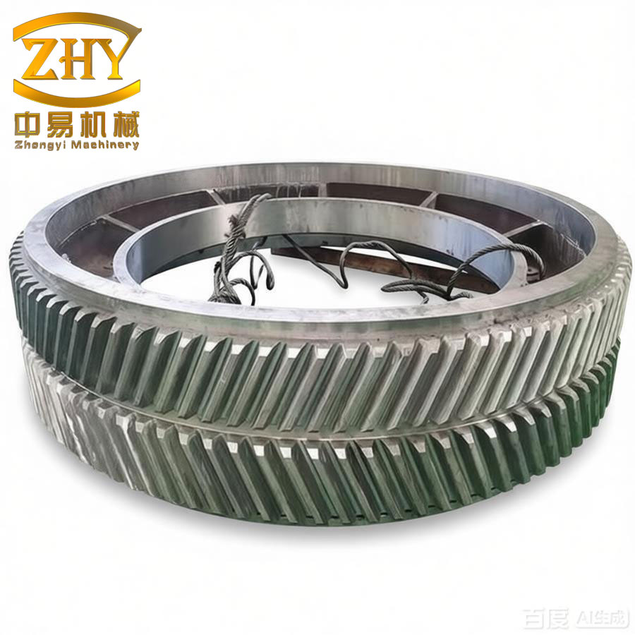
We anticipate that these results will be widely used in the design and manufacturing of herringbone gears, contributing to better performance and reduced material waste. Future work may extend the tables to include other helix angles and module sizes, as well as to investigate the influence of hob wear on the required relief groove width for herringbone gears.