
In the realm of automotive transmission manufacturing, the gear shaving process is a critical finishing operation employed to enhance the surface quality, geometric accuracy, and noise performance of gear teeth. However, a persistent and significant challenge arises during the gear shaving of low-tooth-count cylindrical gears, typically those with 12 to 17 teeth commonly found in passenger vehicle transmissions. This challenge manifests as a distinct defect known as mid-section profile depression, or “profile hollowing,” on the tooth flank. This defect is not merely a cosmetic issue; it fundamentally degrades transmission performance by increasing transmission error, which acts as a primary excitation source for gear whine and vibration. Furthermore, it leads to a non-uniform distribution of contact stress along the tooth profile. In durability testing, this stress concentration often results in premature pitting, crack initiation, and eventually, spalling and catastrophic failure of the gear.
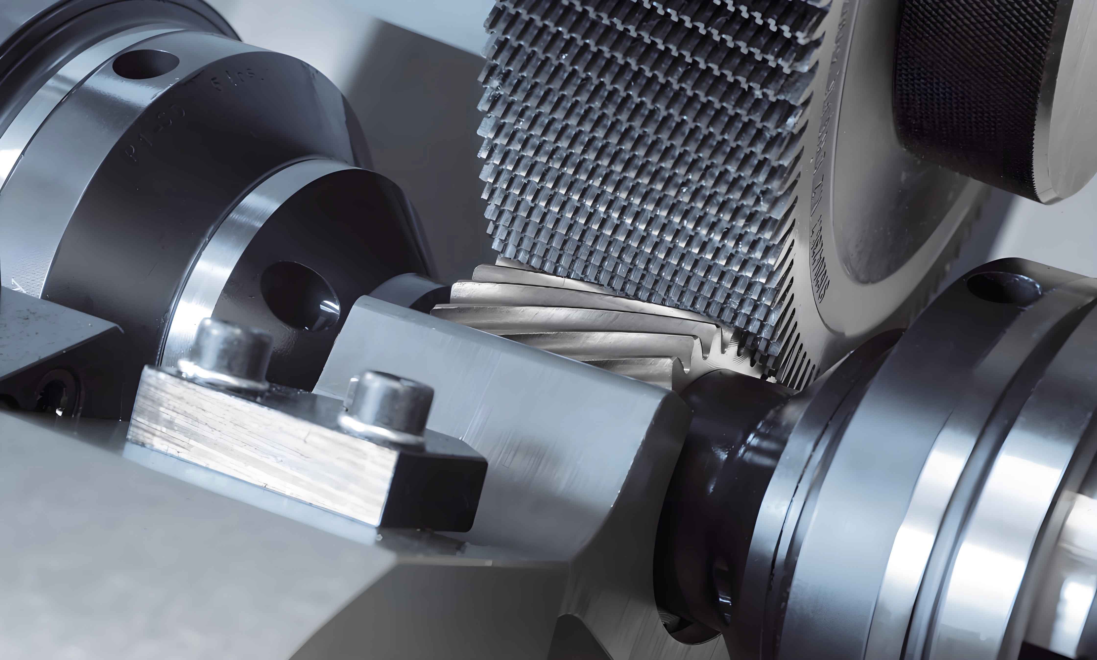
Traditionally, corrective measures for this gear shaving defect are reactive, applied only after the problem is detected on the production line. These measures predominantly involve optimizing the shaving cutter’s profile modifications, such as applying a large crown or a compensating profile. While these methods can mitigate the symptom, they do not address the root cause. The crowned profile merely distributes the error, and the compensating profile wears quickly, allowing the hollow to reappear after a limited number of components are processed. This paper presents a proactive, principle-driven methodology to suppress the onset of profile hollowing by fundamentally reducing force imbalance during the gear shaving process. This is achieved through the strategic design of the shaving cutter’s modification coefficient, supported by dynamic simulation and experimental validation.
The Root Cause: Force Imbalance in Gear Shaving
The genesis of profile hollowing in low-tooth-count gears during gear shaving lies in the dynamic force imbalance inherent in their meshing with the shaving cutter. This imbalance is intrinsically linked to the transverse contact ratio, $\epsilon_{\alpha}$, between the work gear and the shaving cutter.
For a standard gear shaving process involving a spur or helical gear and a helical shaving cutter, the contact ratio is often less than 2 for low-tooth-count, large-module combinations. This leads to an alternating meshing pattern throughout the engagement cycle. The meshing transitions between four distinct states:
- Single-tooth on the gear meshing with single-tooth on the cutter.
- Single-tooth on the gear meshing with double-teeth on the cutter.
- Double-teeth on the gear meshing with single-tooth on the cutter.
- Double-teeth on the gear meshing with double-teeth on the cutter.
The crux of the problem lies in states 2 and 3, which represent conditions of load imbalance. During these phases, the total cutting force is not symmetrically distributed. A critical point occurs near the pitch line region where the transition between single and double contact happens. At this point, the force exerted by the shaving cutter on the gear tooth flank can create a disproportionately high material removal rate, leading to the characteristic depression. This phenomenon is schematically represented by an imbalance in the force vectors ($F_{1′}$, $F_{2′}$, $F_{3′}$) acting at different points (1′, 2′, 3′) along the tooth profile during the gear shaving cycle.
Furthermore, this imbalance has a directional bias. The gear shaving process distinguishes between the “drive side” and “coast side” (or “driven side”) of the gear tooth. The force imbalance typically results in significantly more material being removed from the drive side flank. In severe cases, this can lead to shaving interference at the root of the drive side, while the coast side may remain inadequately finished, creating a lopsided tooth geometry.
The objective, therefore, shifts from correcting the hollow to preventing its formation. The ideal state is “balanced gear shaving,” where the theoretical contact pattern avoids prolonged periods of single-tooth/single-tooth or double-tooth/double-tooth engagement that bracket the imbalanced states. For practical purposes, we aim for “quasi-balanced gear shaving,” a condition where the zones of imbalanced meshing are minimized to an extent that they do not induce a measurable profile hollow. The key to achieving this lies in manipulating the meshing conditions through the design of the shaving cutter, specifically its profile shift coefficient ($x$), in relation to the work gear.
Dynamic Simulation of the Gear Shaving Process
To predict and optimize the gear shaving conditions before physical tooling and cutting trials, dynamic simulation is indispensable. For this study, the MASTA software’s dedicated gear shaving dynamics simulation module was employed. This module models the complex interaction between the shaving cutter and the work gear, accounting for the changing contact conditions, force distributions, and resulting material removal across the tooth flank. The simulation tracks the “force ratio”—a metric representing the relative cutting force distribution—against the roll angle throughout the engagement.
A specific transmission’s 12-tooth reverse idler gear was selected as the case study. The simulation parameters included the exact geometry of the work gear, the initial shaving cutter design, and crucially, the progressive wear and re-sharpening of the shaving cutter over its life. The cutter re-sharpening regimen, involving defined reductions in tooth thickness and tip diameter per sharpening, was strictly input according to manufacturer specifications. The analysis focused on how the imbalanced meshing zone evolved as the cutter was repeatedly sharpened, changing its effective geometry and meshing points with the work gear.
The simulation first considered the ideal, nominal gear geometry. The results, summarized in the table below, show the evolution of the force imbalance profile as the shaving cutter progresses from new to fully worn.
| Cutter State | Force Ratio Plot Characteristics | Key Observation on Imbalance Zone |
|---|---|---|
| New Cutter | Pronounced, deep negative trough in mid-region. | Large imbalance zone, high risk of hollow. |
| After 5 Sharpenings | Trough becomes shallower and narrower. | Imbalance zone is reducing. |
| After 10 Sharpenings | Negative trough is very shallow. | Imbalance zone is minimal. |
| After 15 Sharpenings | Profile is nearly flat or shows slight positive hump. | Imbalance zone is negligible or beneficial. |
| End of Life | Force ratio profile is flat or positively balanced. | Condition of quasi-balanced gear shaving achieved. |
The formula for the transverse contact ratio, central to this issue, is given by:
$$
\epsilon_{\alpha} = \frac{1}{2\pi} \left[ z_1 (\tan\alpha_{a1} – \tan\alpha_{w}’) \pm z_2 (\tan\alpha_{a2} – \tan\alpha_{w}’) \right]
$$
where $z_1, z_2$ are tooth numbers, $\alpha_{a1}, \alpha_{a2}$ are tip profile angles, and $\alpha_{w}’$ is the working pressure angle. For gear shaving of a spur gear ($z_1$) with a helical cutter ($z_2$), the “$\pm$” becomes “$+$”. The goal is to design the cutter such that even with $\epsilon_{\alpha} < 2$, the Start of Active Profile (SAP) and End of Active Profile (EAP) points are positioned to minimize the roll angle span where single-double or double-single contact dominates.
Since manufacturing errors are inevitable, the simulation was augmented with tolerance effects. The positions of the SAP and EAP points on the work gear were varied within their tolerance bands. The results were insightful and highlighted the sensitivity of the gear shaving process to these points:
- For a new cutter: When SAP is at its upper tolerance limit and EAP at its lower limit, the imbalance was less severe. Conversely, with SAP low and EAP high, a pronounced hollowing tendency was predicted.
- For a nearly worn cutter: This sensitivity flipped. A high SAP point could lead to an emerging imbalance zone, indicating that the “sweet spot” for quasi-balanced gear shaving shifts throughout the cutter’s life.
This analysis confirms that simply changing the shaving cutter’s profile shift coefficient can move the operational window of the gear shaving process into a quasi-balanced state for a significant portion of the cutter’s life.
Experimental Validation of Gear Shaving Optimization
To validate the dynamic simulation findings, a practical gear shaving test was conducted on the same Z12 gear. To isolate the effect of the cutter’s basic geometry change (due to sharpening) from the effect of profile modification, the shaving cutters were re-sharpened strictly according to the dimensional schedule (e.g., reducing tooth thickness by 0.05 mm per side) while meticulously preserving the original lead and profile crowning modifications from the new cutter state. The initial modified profile had a slight negative bias and a small hollow.
Gear shaving trials were conducted at three distinct gear tooth thickness conditions: upper limit, nominal, and lower limit. This intentionally varied the effective SAP point position on the shaved gear, allowing direct correlation with the simulation scenarios that included tolerance effects.
| Gear Tooth Thickness Condition | Effective SAP Point | Measured Profile Hollow Depth | Correlation with Simulation |
|---|---|---|---|
| Upper Limit | Relatively Higher | Smaller Hollow (~ -1 to -2 μm) | Matches prediction for “SAP High” case. |
| Nominal | Nominal | Moderate Hollow (~ -3 μm) | Consistent with nominal simulation. |
| Lower Limit | Relatively Lower | Larger Hollow (~ -3 to -4 μm) | Matches prediction for “SAP Low” case. |
The cutter was then progressively sharpened according to plan. After each sharpening, gears were shaved at the nominal tooth thickness target. The results demonstrated a clear trend:
| Cutter Sharpening Count | Cutter Tooth Thickness Reduction (Cumulative) | Measured Profile Hollow Depth (Nominal Gear) | Observation |
|---|---|---|---|
| 0 (New) | 0 mm | Approx. -3 μm | Pronounced hollow present. |
| 2 | ~0.10 mm | Approx. -2 μm | Hollow is diminishing. |
| 4 | ~0.20 mm | Approx. -1 μm | Hollow is very slight. |
| 5 | ~0.25 mm | ~0 μm | Hollow effectively eliminated. Quasi-balanced gear shaving achieved. |
The experimental data conclusively confirmed the simulation predictions: 1) The sensitivity of the gear shaving hollow to the SAP point position, and 2) The gradual reduction and eventual elimination of the hollow as the shaving cutter is sharpened, corresponding to a systematic change in its effective profile shift and the consequent shift in the meshing dynamics toward a quasi-balanced state.
Integrated Optimization Strategy for Gear Shaving
The study demonstrates that solving the low-tooth-count gear shaving hollow problem requires an integrated, forward-looking design approach rather than post-process correction. The size of the imbalanced zone during gear shaving is governed by the effective length of contact and the precise locations of the SAP and EAP points. These are not solely determined by the finished gear design but are a consequence of the entire manufacturing chain: the gear design specification, the basic rack design of the hobbing cutter, the amount of stock left for gear shaving, and critically, the profile shift coefficient of the shaving cutter.
Therefore, an optimal strategy involves a holistic “gear-hob-shaving cutter” integrated design. The workflow can be summarized as follows:
- Define Performance Envelope: Establish the required final gear geometry and tolerance stack-up (SAP/EAP zones).
- Model Gear Shaving Dynamics: Use simulation software (like MASTA) to model the gear shaving process with initial tooling assumptions.
- Optimize Cutter Parameters: Iteratively adjust the shaving cutter’s profile shift coefficient ($x_{shaver}$) and the stock allowance to find a combination that maximizes the operational window (across expected gear tolerance ranges and cutter wear) for quasi-balanced gear shaving.
This can be framed as a constrained optimization:
$$
\min_{x_s, \Delta} \left( \max_{\text{SAP, EAP, wear}} |\text{Imbalance Zone}_{\text{roll angle}}| \right)
$$
Subject to: Final gear spec constraints, Hobbling feasibility, Shaving cutter strength/life constraints.
Where $x_s$ is the shaving cutter profile shift and $\Delta$ is the stock allowance. - Select Process: Favor radial gear shaving over axial where possible for low-tooth-count gears. In radial gear shaving, the continuous radial infeed causes the imbalance zone to traverse the tooth face height more uniformly, often resulting in a less pronounced hollow compared to the fixed cross-axis angle in axial gear shaving.
- Define Cutter Life Management: The simulation provides a map of imbalance vs. cutter sharpening state. This map can guide production planning, indicating during which periods of the cutter’s life the most critical parts should be run to ensure consistent, high-quality gear shaving results.
Conclusion
This research establishes a robust, simulation-driven methodology to proactively address the chronic problem of profile hollowing in low-tooth-count cylindrical gears during the gear shaving process. By shifting the focus from corrective profile modification on the shaving cutter to a principle-based reduction of dynamic force imbalance, a more fundamental and durable solution is achieved. The dynamic simulation of the gear shaving process accurately predicts the relationship between shaving cutter geometry (as it changes with sharpening), work gear tolerances, and the resulting meshing imbalance. Experimental validation on a Z12 transmission gear confirmed these predictions, showing that strategic management of the cutter’s effective profile shift can lead to a state of quasi-balanced gear shaving where the mid-section depression is eliminated.
The key takeaway is that the success of the gear shaving operation for challenging geometries like low-tooth-count gears must be designed in from the outset. It requires a synergistic consideration of the final gear design, the pre-shaving hobbling process, and the initial design and life-cycle management of the shaving cutter itself. This integrated approach, powered by dynamic simulation, moves gear shaving from an art of correction to a science of prediction and optimization, leading to higher quality, more reliable transmission components.