
In the field of mechanical transmission, hyperbolic gears, also known as hypoid gears, are widely recognized for their superior performance, including high transmission ratios, increased overlap ratios, strong load-bearing capacity, smooth operation, and high efficiency. These advantages make them indispensable in applications such as aviation, automotive, and engineering machinery. The meshing performance of hyperbolic gears is primarily evaluated through tooth contact patterns and transmission error curves, which directly impact the operational reliability and lifespan of equipment. However, achieving ideal tooth contact characteristics, especially for gears manufactured using the duplex helical method (also known as the completing method), poses significant challenges due to difficulties in synchronously adjusting both flanks. This study aims to investigate the interaction among installation errors, helical motion coefficients, and meshing performance for hyperbolic gear pairs processed via the duplex helical method, employing numerical analysis and mathematical modeling to provide insights for high-quality manufacturing.
The duplex helical method introduces a helical motion coefficient as a key machining parameter, which involves a feed motion of the cutter along the cradle axis during processing. This motion dynamically alters the machine center-to-back (MCB) distance, enabling precise control over tooth contact characteristics. Compared to traditional “five-cut” methods, the duplex helical method offers enhanced flexibility in pre-contacting tooth patterns, yet its widespread adoption in practical production remains limited. This research builds upon existing literature by integrating numerical analysis with tooth surface topology tools, utilizing FORTRAN and MATLAB hybrid programming for tooth contact analysis (TCA) to explore the effects of helical motion coefficients on geometric morphology, generating line positions, and contact behavior under various installation errors.
To establish a foundational understanding, the mathematical model for gear cutting and assembly is developed using vector methods. The coordinate systems for pinion cutting are defined, with the cutter coordinate system \( S_0 \{X_0, Y_0, Z_0\} \) fixed to the cutter head, where the cutter axis \( c_0 \) aligns with \( Z_0 \). The straight-line cutter profile for the pinion consists of two parts: part (a) as the main working section and part (b) as the arc for generating the fillet. Key parameters include the fillet radius \( \rho_1 \), tool pressure angle \( \alpha_{01} \), nominal cutter radius \( r_{01} \), blade edge distance \( p_{w1} \), tip radius \( r_{c1} \), and parameters \( s_1 \), \( \lambda_1 \), and \( \theta_1 \) representing the cutter profile and rotation. The position vector and unit normal vector for the generating surface of the pinion’s straight-line cutter profile in the cutter coordinate system are expressed as:
$$ \mathbf{r}_{01} = \begin{bmatrix} (-r_{c1} \pm s_1 \sin \alpha_{01}) \sin \theta_1 \\ (-r_{c1} \pm s_1 \sin \alpha_{01}) \cos \theta_1 \\ s_1 \cos \alpha_{01} \end{bmatrix} $$
$$ \mathbf{n}_{01} = \begin{bmatrix} -\cos \alpha_{01} \sin \theta_1 \\ -\cos \alpha_{01} \cos \theta_1 \\ \mp \sin \alpha_{01} \end{bmatrix} $$
where the “+” sign denotes the concave side (drive side) and the “-” sign denotes the convex side (coast side) of the hyperbolic gears.
The pinion tooth surface generation involves multiple coordinate transformations. The machine coordinate system \( S_m \{X_m, Y_m, Z_m\} \) is rigidly fixed to the machine, with the cradle rotating about the \( Z_m \)-axis. The pinion axis direction unit vector is \( \mathbf{p}_1 \), and the generating gear axis direction is \( \mathbf{g}_1 \). The position vector and unit normal vector in the machine coordinate system are derived through rotational transformations:
$$ \mathbf{r}_{m01} = \mathbf{R}[z, -q] \left\{ \mathbf{R}[z, J_1] \mathbf{R}[x, I_1] \mathbf{r}_{01} + [S_{r1} \ 0 \ 0]^T \right\} $$
$$ \mathbf{n}_{m01} = \mathbf{R}[z, -q] \mathbf{R}[z, J_1] \mathbf{R}[x, I_1] \mathbf{n}_{01} $$
where \( q = q_1 + \Delta q_1 \), with \( q_1 \) as the initial angular cutter position and \( \Delta q_1 \) as the cradle rotation angle. \( \mathbf{R}[z, -q] \) denotes the rotation matrix about the z-axis by angle \( -q \). Due to the helical motion, the machine center-to-back distance is expressed as:
$$ X_B = X_{B1} – H_{l1} \Delta q_1 $$
where \( H_{l1} \) is the helical motion coefficient, a critical parameter in the duplex helical method for hyperbolic gears.
The pinion tooth surface equation and its unit normal vector are obtained by substituting the relative position vector from the pinion crossing point \( O_1 \) to the machine center \( O_m \), denoted as \( \mathbf{m}_1 \), and the relative angular velocity \( \boldsymbol{\omega}_{p1} \) and relative motion velocity \( \mathbf{v}_{p1} \) between the generating gear and workpiece into the engagement equation:
$$ \begin{cases} \mathbf{r}_1 = \mathbf{r}_{m01} + \mathbf{m}_1 \\ \mathbf{n}_1 = \mathbf{n}_{m01} \end{cases} $$
This formulation allows for the discretization of the tooth surface into grid points for subsequent analysis. For instance, the tooth surface can be divided into i rows and j columns, totaling \( i \times j \) points, to facilitate the construction of ease-off topology maps and contact analysis.
To illustrate, consider a hyperbolic gear pair with a pinion of 7 teeth and a gear of 43 teeth (7 × 43). The geometric and machining parameters are summarized in the following tables, which are essential for understanding the design and manufacturing of hyperbolic gears using the duplex helical method.
| Parameter Name | Pinion | Gear |
|---|---|---|
| Number of Teeth | 7 | 43 |
| Module (mm) | 6.860 | 6.860 |
| Face Width (mm) | 43.51 | 40.00 |
| Offset Distance (mm) | 25.40 | |
| Shaft Angle (°) | 90° | |
| Spiral Angle (°) | 50.03 | 38.80 |
| Mean Cone Distance (mm) | 129.99 | 130.44 |
| Hand of Spiral | LH | RH |
| Manufacturing Method | Duplex Generated | Generated |
| Pitch Cone Angle (°) | 11.20 | 78.58 |
| Face Cone Angle (°) | 14.30 | 79.07 |
| Root Cone Angle (°) | 10.73 | 75.43 |
| Parameter Name | Pinion | Gear |
|---|---|---|
| Cutter Diameter (mm) | 223.76 | 228.60 |
| Outer Blade Pressure Angle (°) | 20.00 | 20.00 |
| Inner Blade Pressure Angle (°) | 25.00 | 25.00 |
| Blade Edge Distance (mm) | 2.54 | 3.05 |
| Radial Setting (mm) | 102.80 | 105.18 |
| Cutter Tilt Angle (°) | 3.58 | 0.00 |
| Cutter Swivel Angle (°) | 196.29 | 197.60 |
| Vertical Setting (mm) | 23.11 | -1.48 |
| Machine Root Angle (°) | 11.43 | 75.43 |
| Horizontal Setting (mm) | -1.99 | -1.10 |
| Machine Center-to-Back (mm) | 4.81 | 0.24 |
| Ratio of Roll | 6.07 | 1.01 |
| Center Roll Position (°) | 65.58 | 56.40 |
| Helical Motion Coefficient (mm/rad) | -1.4754 | 0.00 |
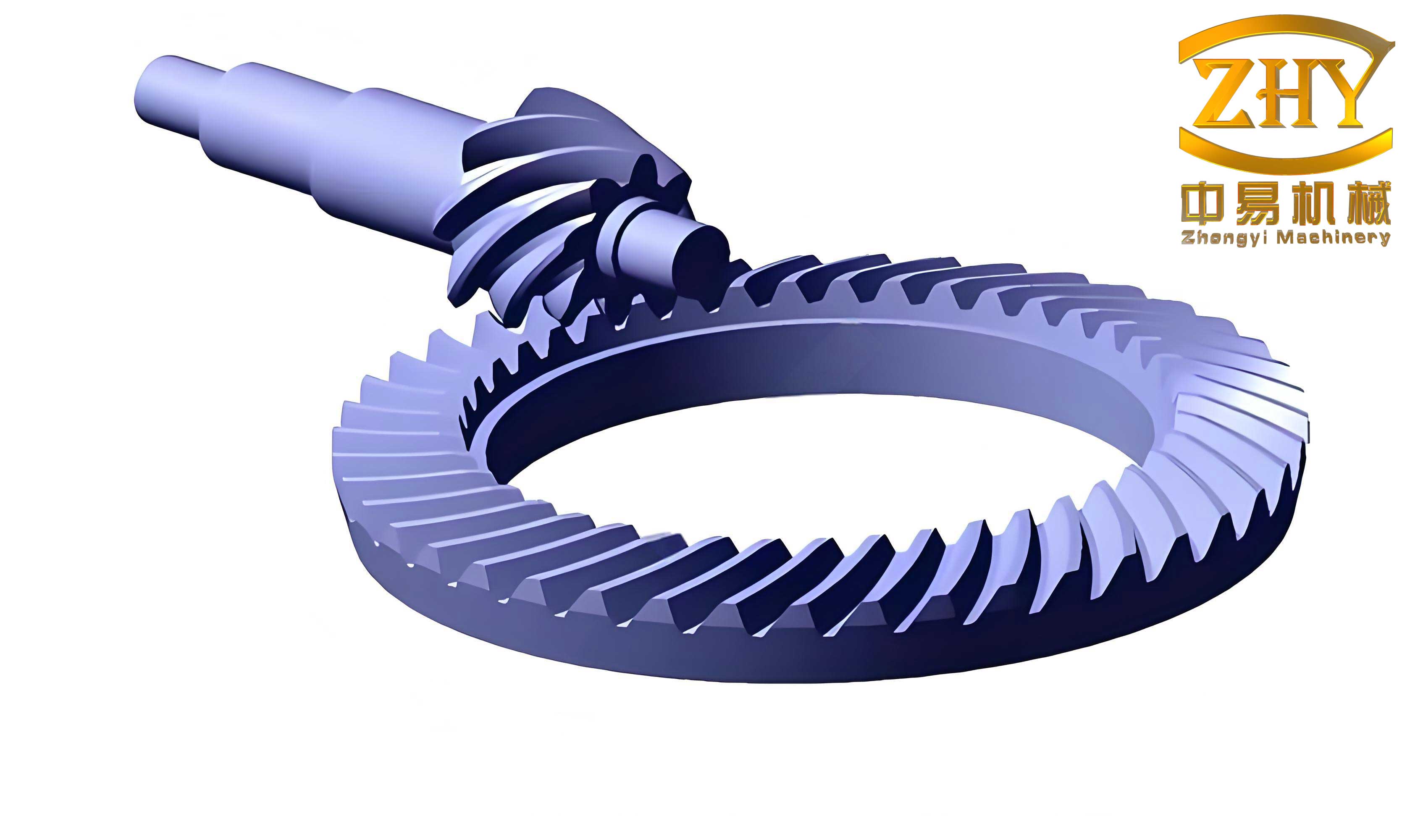
The geometric complexity of hyperbolic gears necessitates precise modeling, and the inclusion of the helical motion coefficient in the duplex helical method introduces a dynamic element that influences tooth surface generation. The following image provides a visual representation of hyperbolic gears, highlighting their unique geometry and application in transmission systems.
With the mathematical model established, the meshing performance analysis focuses on the effects of the helical motion coefficient and installation errors. The helical motion coefficient is pivotal in controlling diagonal contact and contact path length, thereby enhancing the load distribution and operational stability of hyperbolic gears. To study its impact, a series of numerical cases are defined by varying the helical motion coefficient while keeping other machining parameters constant, as shown in the table below.
| Case | Change in Helical Motion Coefficient (mm/rad) | Helical Motion Coefficient (mm/rad) |
|---|---|---|
| 1 (Baseline) | No change | -1.4754 |
| 2 | Decrease by 0.5 | -1.9754 |
| 3 | Increase by 0.5 | -0.9754 |
| 4 | Decrease by 1.0 | -2.4754 |
| 5 | Increase by 1.0 | -0.4754 |
The tooth contact analysis (TCA) for these cases reveals significant trends. The contact patterns and transmission error curves are computed using the discretized tooth surface points. For hyperbolic gears, the contact trajectory and maximum transmission error serve as key indicators of meshing performance. The results indicate that as the helical motion coefficient increases, the contact path on the drive side elongates along the lengthwise direction, with an increased direction angle, whereas a decrease shortens the path and reduces the angle. This behavior is attributed to the diagonal modification induced by the helical motion, which differentially affects the drive and coast sides of hyperbolic gears. The maximum transmission error on the drive side decreases with increasing helical motion coefficient, while on the coast side, it follows a similar trend but with greater sensitivity. These findings underscore the role of the helical motion coefficient in pre-contacting tooth contact characteristics for hyperbolic gears.
To further quantify the geometric modifications, an ease-off topology model is constructed. The ease-off, defined as the normal distance between the analyzed tooth surface and a reference tooth surface, provides insights into the surface morphology. For a grid point \( (i, j) \), the ease-off value \( m_{ij} \) is calculated as:
$$ m_{ij} = (\mathbf{r}_{ij}^k – \mathbf{r}_{ij}^1) \cdot \mathbf{n}_{ij}^1 $$
where \( \mathbf{r}_{ij}^1 \) and \( \mathbf{n}_{ij}^1 \) are the position vector and unit normal vector of the baseline case (Case 1), and \( \mathbf{r}_{ij}^k \) is the position vector for Case k (k = 2 to 5). The resulting ease-off maps demonstrate that the helical motion applies a diagonal modification: on the drive side, modification occurs from the root at the heel to the tip at the toe, while on the coast side, it occurs from the tip at the heel to the root at the toe. The modification magnitude can exceed 200 μm in critical regions, highlighting the substantial influence of the helical motion coefficient on the tooth surface geometry of hyperbolic gears.
Another critical aspect is the generating line, which represents the cutter path during grinding and affects the micro-geometry of hyperbolic gears. The generating line position is determined by the cutter profile parameter \( s_1 \). For a given \( s_1 \), the corresponding point on the tooth surface is computed through polynomial fitting. The relationship between the grid point coordinates \( (x_i, y_i) \) and \( s_1 \) is expressed as:
$$ y_i = p_1 s_1^5 + p_2 s_1^4 + p_3 s_1^3 + p_4 s_1^2 + p_5 s_1 + p_6 $$
where \( p_1 \) to \( p_6 \) are constants derived from the geometric model. By analyzing different helical motion coefficients, the generating lines shift: on the drive side, as the helical motion coefficient increases, generating lines near the heel move toward the root, whereas on the coast side, they move toward the tip. This shift pattern is symmetric about the baseline case and further elucidates the modification mechanism of the duplex helical method for hyperbolic gears.
Installation errors are inevitable in practical applications and can detrimentally affect the meshing performance of hyperbolic gears. The primary installation parameters include pinion mounting distance \( H \), pinion offset distance \( V \), gear mounting distance \( J \), and shaft angle \( \Sigma \). The actual installed values, denoted with primes, are given by:
$$ \begin{cases} H’ = H + \Delta H \\ V’ = V + \Delta V \\ J’ = J + \Delta J \\ \Sigma’ = \Sigma + \Delta \Sigma \end{cases} $$
where \( \Delta H \), \( \Delta V \), \( \Delta J \), and \( \Delta \Sigma \) are the adjustment amounts. Typical ranges for these adjustments are provided in the table below, based on practical assembly considerations for hyperbolic gears.
| Parameter Name | Adjustment Range |
|---|---|
| Pinion Mounting Distance Adjustment \( \Delta H \) (mm) | -0.1 to 0.1 |
| Pinion Offset Distance Adjustment \( \Delta V \) (mm) | -0.1 to 0.1 |
| Gear Mounting Distance Adjustment \( \Delta J \) (mm) | -0.1 to 0.1 |
| Shaft Angle Adjustment \( \Delta \Sigma \) (°) | -0.5 to 0.5 |
The effects of these installation errors on tooth contact patterns and transmission errors are systematically analyzed. For instance, an increase in \( \Delta H \) shifts the drive-side contact pattern toward the toe and tip, potentially causing edge contact at the tip if excessive, while the coast-side pattern shifts toward the heel and tip. Conversely, a decrease in \( \Delta H \) moves the drive-side pattern toward the heel and root. The maximum transmission error on the drive side increases with \( \Delta H \), whereas on the coast side, it decreases. Similar analyses are conducted for \( \Delta V \), \( \Delta J \), and \( \Delta \Sigma \), revealing that each error type induces distinct shifts in contact patterns and changes in transmission error magnitudes. These results emphasize the importance of precise installation to maintain optimal meshing performance in hyperbolic gears.
To validate the numerical models and findings, practical machining and rolling tests are conducted on the 7 × 43 hyperbolic gear pair. The gears are manufactured using a CNC hypoid gear grinding machine, with the duplex helical method parameters applied. The grinding process involves setting the helical motion coefficient and other adjustments as per the design. After machining, the gear pair is assembled on a rolling tester under specified conditions: a rotational speed of 1440 rpm and a load of 20 Nm. The contact patterns observed on both the drive and coast sides align closely with the numerical predictions, showing contact areas centered on the tooth surface with a diagonal orientation. This experimental verification confirms the accuracy of the mathematical models and demonstrates the effectiveness of the helical motion in pre-contacting tooth contact characteristics for hyperbolic gears.
In conclusion, this comprehensive study on hyperbolic gears manufactured via the duplex helical method provides valuable insights into the interplay between machining parameters, installation errors, and meshing performance. The helical motion coefficient is identified as a critical factor for controlling diagonal contact and contact path length, with distinct modification principles applied to the drive and coast sides. The mathematical models, including tooth surface generation, ease-off topology, and generating line analysis, offer robust tools for design and optimization. Installation errors significantly influence contact patterns and transmission errors, underscoring the need for precise assembly in applications involving hyperbolic gears. The experimental validation reinforces the reliability of the numerical approaches. Future work could explore multi-objective optimization incorporating ease-off modifications to further enhance the load capacity and efficiency of hyperbolic gears, paving the way for advanced manufacturing techniques in high-performance transmission systems.