
The reliable operation of mechanical transmission systems is paramount in industrial applications, and spur gears constitute one of the most fundamental and widely used components. During operation, these systems are subjected to dynamic excitations arising primarily from the periodic variation in the number of gear teeth in contact. This inherent characteristic, combined with complex loading conditions, makes spur gears susceptible to various failure modes such as root cracks, surface pitting, and even tooth breakage. Understanding the dynamic behavior of spur gears under fault conditions is therefore crucial for effective health monitoring and predictive maintenance strategies. A key challenge in achieving this lies in the accurate mathematical representation of the system’s internal excitation, specifically the time-varying mesh stiffness (TVMS). Traditional dynamic models often employ simplified geometries, particularly for the critical tooth root fillet region, which can lead to significant inaccuracies in stiffness calculation and, consequently, in the predicted dynamic response. This inaccuracy hinders the development of precise diagnostic algorithms.
This article addresses this challenge by presenting a comprehensive multi-fault dynamic modeling methodology. The core contribution is a refined, high-fidelity model for calculating the TVMS of spur gear pairs. The model integrates several critical aspects: the elastic deformation of the gear tooth modeled as a non-uniform cantilever beam, the flexibility of the gear body surrounding the root, the localized Hertzian contact deformation, and—most importantly—an accurate geometric representation of the tooth root transition curve. Utilizing the energy method, this approach enables a more precise and computationally efficient determination of the TVMS, which serves as the primary excitation in the dynamic model. A lumped-parameter model is then established to simulate the coupled translational-torsional vibrations of the gear pair. The influence of different fault types—root cracks, surface pitting, and missing teeth—on the TVMS is analytically derived and incorporated into the model. Finally, the simulated dynamic responses are generated and their spectral characteristics are analyzed and compared with experimental measurements from a dedicated test rig, validating the proposed methodology’s effectiveness in capturing fault-specific features.
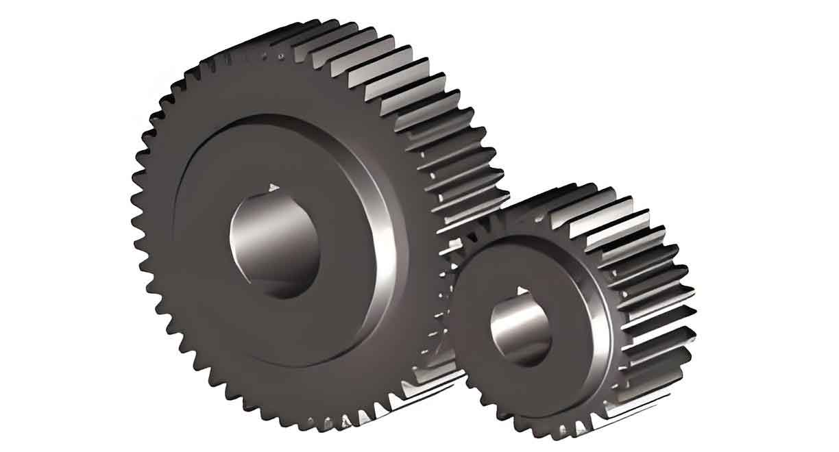
Theoretical Foundation: Dynamics of Spur Gear Pairs
The dynamic behavior of a pair of spur gears is modeled using a lumped-parameter approach, considering six degrees of freedom: two translational motions (along the line-of-action and the off-line direction) and one torsional motion for each gear. A coupled dynamic model accounting for friction at the mesh interface is employed. The coordinate system defines displacements \(x_p\), \(y_p\) for the pinion and \(x_g\), \(y_g\) for the gear, along with rotational displacements \(\theta_p\) and \(\theta_g\).
The equations of motion are derived from Newton’s second law:
$$
\begin{aligned}
m_p \ddot{x}_p + c_{px} \dot{x}_p + k_{px} x_p &= F_f \\
m_g \ddot{x}_g + c_{gx} \dot{x}_g + k_{gx} x_g &= F_f \\
m_p \ddot{y}_p + c_{py} \dot{y}_p + k_{py} y_p &= F_p \\
m_g \ddot{y}_g + c_{gy} \dot{y}_g + k_{gy} y_g &= F_g \\
I_p \ddot{\theta}_p &= T_p + M_p – F_p R_p \\
I_g \ddot{\theta}_g &= -T_g + M_g + F_g R_g
\end{aligned}
$$
where the subscripts \(p\) and \(g\) denote the pinion and gear, respectively. \(m\) is mass, \(I\) is mass moment of inertia, and \(R\) is the base circle radius. \(k_{px}, k_{py}, k_{gx}, k_{gy}\) are the supporting stiffnesses in the \(x\) and \(y\) directions, with corresponding damping coefficients \(c_{px}, c_{py}, c_{gx}, c_{gy}\). \(T_p\) and \(T_g\) are the external torque loads. \(F_f\) is the friction force at the meshing interface, and \(M_p\), \(M_g\) are the moments induced by this friction. The dynamic meshing force components \(F_p\) and \(F_g\) along the line-of-action are given by:
$$
F_p = -F_g = c_m \dot{y} + k_m y
$$
Here, \(y = y_p – y_g + R_p \theta_p – R_g \theta_g\) represents the relative dynamic displacement along the line-of-action, \(k_m(t)\) is the time-varying mesh stiffness, and \(c_m\) is the mesh damping, often estimated as a fraction of the critical damping. The accurate computation of \(k_m(t)\) is the cornerstone for predicting the dynamic response of the spur gear system accurately.
High-Fidelity Time-Varying Mesh Stiffness Calculation for Spur Gears
The total TVMS for a spur gear pair is obtained by considering the series compliance of each engaged tooth pair. For a single tooth pair at a given contact point, the equivalent stiffness \(K\) is calculated from the total deflection \(\delta_{total}\) under the action of the normal load \(F\): \(K = F / \delta_{total}\). This total deflection is a superposition of deformations from three primary sources: 1) tooth body deflection, 2) gear body deflection at the root, and 3) Hertzian contact deflection.
$$
\delta_{total} = \delta_{tooth} + \delta_{fillet} + \delta_{hertz} = (\delta_b + \delta_s + \delta_a) + \delta_f + \delta_h
$$
1. Tooth Body Deflection (\(\delta_{tooth}\))
The tooth is modeled as a non-uniform cantilever beam with a variable cross-section along its height. The deflection at the load application point consists of bending (\(\delta_b\)), shear (\(\delta_s\)), and axial compression (\(\delta_a\)) components. Using the energy method (Castigliano’s theorem), these are expressed as integrals along the tooth profile from the root to the load point:
$$
\begin{aligned}
\delta_b &= \frac{F}{K_b} = F \int_{0}^{d} \frac{[(d – x) \cos\alpha_1 – h \sin\alpha_1]^2}{E I_x} dx \\
\delta_s &= \frac{F}{K_s} = F \int_{0}^{d} \frac{1.2 \cos^2\alpha_1}{G A_x} dx \\
\delta_a &= \frac{F}{K_a} = F \int_{0}^{d} \frac{\sin^2\alpha_1}{E A_x} dx
\end{aligned}
$$
where \(E\) is Young’s modulus, \(G\) is the shear modulus, \(\alpha_1\) is the load application angle relative to the tooth centerline, \(d\) is the distance from the root to the load point, \(h\) is the distance from the load point to the tooth centerline. \(A_x\) and \(I_x\) are the area and area moment of inertia of the tooth cross-section at a distance \(x\) from the root. Their accurate determination relies on the precise tooth profile geometry.
2. Precise Tooth Root Transition Curve Geometry
A significant advancement in this model is the accurate representation of the tooth root fillet, which is typically generated by the tip of the cutting tool (hob or rack cutter). The transition from the active involute profile to the root circle is not a simple arc but a trochoid. For a rack cutter, the transition curve can be described by the following parametric equations, providing the coordinates of any point on the fillet relative to the gear center:
$$
\begin{aligned}
x(\varphi) &= r \cos\varphi – \left( \frac{a_1}{\sin\gamma} + r_p \right) \sin(\gamma – \varphi) \\
y(\varphi) &= r \sin\varphi – \left( \frac{a_1}{\sin\gamma} + r_p \right) \cos(\gamma – \varphi)
\end{aligned}
$$
Here, \(r\) is the pitch radius, \(r_p\) is the tip radius of the cutting tool, \(a_1\) is the distance from the tool tip to its reference line, and \(\gamma\) is a geometric parameter related to the tool shift. This precise formulation allows for the accurate calculation of \(A_x\) and \(I_x\) throughout the entire tooth, including the critical root region where stress concentration and cracks initiate, leading to a more realistic stiffness profile for the spur gear.
3. Gear Body (Fillet) Deflection (\(\delta_f\))
The deformation of the gear structure surrounding the tooth root, which is not part of the cantilever beam, also contributes to the overall compliance. An empirical formula based on a parabola-shaped solid is used for its computational efficiency and accuracy:
$$
\delta_f = \frac{F \cos^2\alpha_1}{W E} \left[ L^* \left( \frac{u_f}{s_f} \right)^2 + M^* \left( \frac{u_f}{s_f} \right) + P^* (1 + Q^* \tan^2\alpha_1) \right]
$$
where \(W\) is the face width, \(u_f\) and \(s_f\) are geometric parameters defined at the tooth root, and \(L^*, M^*, P^*, Q^*\) are coefficients that depend on the tooth’s geometric angles.
4. Hertzian Contact Deflection (\(\delta_h\))
The local deformation at the point of contact between two teeth is given by the classical Hertzian contact theory for two parallel cylinders. This stiffness component is independent of the contact position:
$$
\delta_h = \frac{4F(1-\nu^2)}{\pi E W}
$$
where \(\nu\) is Poisson’s ratio.
5. Mesh Stiffness of a Gear Pair
For a single pair of spur gear teeth in contact, the equivalent mesh stiffness \(K_{pair}\) is calculated by considering the combined deflections of both the pinion and gear teeth, with the contact deflection appearing only once:
$$
K_{pair} = \frac{1}{ \frac{1}{K_{p}} + \frac{1}{K_{g}} }
$$
where \(K_{p} = F/\delta_{p}\) and \(K_{g} = F/\delta_{g}\), with \(\delta_{p} = \delta_{b,p}+\delta_{s,p}+\delta_{a,p}+\delta_{f,p}\) and similarly for the gear. The total TVMS \(k_m(t)\) for the spur gear pair is the sum of the stiffnesses of all tooth pairs in simultaneous contact at any given instant, which alternates between one and two pairs for standard spur gears.
Modeling of Common Faults in Spur Gears
The proposed energy method framework is exceptionally well-suited for incorporating localized faults by modifying the geometric parameters \(A_x\) and \(I_x\) in the affected region during the integration process for calculating tooth deflection.
1. Tooth Root Crack Model
A propagating root crack is modeled as a straight line, reducing the effective cross-sectional area and moment of inertia. The crack is defined by its starting point on the root surface, its depth \(q\), and its angle \(\alpha_c\). The effective tooth thickness \(h_x’\) at a section distance \(x\) from the root is reduced if the crack path intersects that section. The modified area \(A_x’\) and moment of inertia \(I_x’\) are:
For \(h_x \le h_q\):
$$
A_x’ = (h_x + h_x)W = 2h_x W; \quad I_x’ = \frac{1}{12}(2h_x)^3 W
$$
For \(h_x > h_q\):
$$
A_x’ = (h_x + h_q)W; \quad I_x’ = \frac{1}{12}(h_x + h_q)^3 W
$$
where \(h_q = h_c – q \sin\alpha_c\), and \(h_c\) is the distance from the crack initiation point to the tooth centerline. These modified values are used in the integrals for \(\delta_b\), \(\delta_s\), and \(\delta_a\) within the cracked section, significantly reducing the local stiffness of the affected spur gear tooth.
2. Surface Pitting Model
Surface pitting is modeled as a localized loss of material on the tooth flank, creating a rectangular pit with length \(a_s\) (along the profile direction), width \(W_s\) (across the face width), and depth \(h_s\). This defect primarily affects the tooth cross-section within the pit’s boundaries. The reductions in effective face width \(\Delta W_x\), area \(\Delta A_x\), and moment of inertia \(\Delta I_x\) at section \(x\) are:
$$
\begin{aligned}
\Delta W_x &=
\begin{cases}
W_s, & \text{if } x \in [\mu – a_s/2, \mu + a_s/2] \\
0, & \text{otherwise}
\end{cases} \\
\Delta A_x &=
\begin{cases}
\Delta W_x \cdot h, & \text{if } x \in [\mu – a_s/2, \mu + a_s/2] \\
0, & \text{otherwise}
\end{cases} \\
\Delta I_x &=
\begin{cases}
\frac{1}{12}\Delta W_x h^3 + \frac{A_x \Delta A_x (h_x – h/2)^2}{A_x – \Delta A_x}, & \text{if } x \in [\mu – a_s/2, \mu + a_s/2] \\
0, & \text{otherwise}
\end{cases}
\end{aligned}
$$
where \(\mu\) is the distance from the root to the center of the pit, and \(h\) is the total tooth height at section \(x\). The corrected properties are \(A_x’ = A_x – \Delta A_x\), \(I_x’ = I_x – \Delta I_x\), and \(W’ = W – \Delta W_x\). When the contact point traverses this pit, a sudden drop in mesh stiffness occurs due to the loss of contact material.
3. Missing Tooth (Breakage) Model
Modeling a missing tooth is straightforward within the TVMS calculation framework. During the angular period where the broken tooth would normally be in contact, its contribution to the total mesh stiffness is null. Effectively, the double-tooth-contact zones adjacent to the missing tooth’s theoretical engagement period become single-tooth-contact zones, and the zone where the missing tooth should be the sole contact becomes a period of no contact, resulting in a significant impact and a large drop in the TVMS for that rotational period.
Simulation Analysis and Validation with Experimental Response
To validate the proposed multi-fault dynamic model for spur gears, a simulation study was conducted and compared against experimental data from a parallel-axis gearbox test rig. The primary parameters of the spur gear pair used are summarized in the table below.
| Parameter | Pinion (Driver) | Gear (Driven) |
|---|---|---|
| Number of Teeth | 23 | 84 |
| Module (mm) | 2 | 2 |
| Pressure Angle (deg) | 20 | 20 |
| Face Width (mm) | 20 | 20 |
| Mass (kg) | 0.22 | 1.90 |
| Moment of Inertia (kg·m²) | 4.858e-5 | 3.509e-3 |
| Rotational Speed (rpm) | 1800 | ~493 |
The pinion rotational speed was set to 1800 rpm, corresponding to a mesh frequency \(f_m = 690\) Hz. Support stiffness and damping values for the bearings were identified via model updating. Vibration acceleration signals were simulated and measured radially on the gearbox housing, with a sampling frequency of 51.2 kHz. The following sections compare the time-domain waveforms and frequency spectra for each fault condition.
1. Root Crack Fault Analysis
A root crack fault was introduced on a pinion tooth, with a crack depth of 1 mm and an angle of 45° starting from the midpoint of the root fillet. Both simulation and experimental results for the cracked spur gear show distinct periodic impacts corresponding to the pinion’s rotational frequency (\(f_p = 30\) Hz). In the frequency domain, the spectrum is dominated by the mesh frequency \(f_m\) and its harmonics. Notably, sidebands appear around these harmonics, spaced at the pinion rotational frequency (\(f_p\)). The modulation is caused by the periodic stiffness reduction introduced by the cracked tooth, which amplitude-modulates the meshing vibration. The simulated response accurately captures this pattern, showing elevated sideband energy, particularly around the second harmonic (\(2f_m\)), which aligns closely with the experimental measurements.
2. Surface Pitting Fault Analysis
A surface pit was modeled on the pinion tooth at the pitch point, with dimensions: length = 1 mm, width = 10 mm, depth = 0.5 mm. Due to the relatively small size of the pit, its effect on the overall dynamics is subtler than a crack. The simulated and experimental time-domain signals show minor, periodic fluctuations in amplitude rather than sharp impacts. In the frequency spectrum, the mesh frequency and its harmonics remain the dominant components. Sidebands at \(f_p\) are present but with much lower amplitude compared to the crack case. The energy distribution is more concentrated, and the fault signature is less pronounced. This consistency between simulation and experiment indicates that the model correctly predicts the milder dynamic modulation caused by localized pitting on the spur gear tooth flank.
3. Missing Tooth Fault Analysis
The missing tooth fault represents a severe condition. In the simulation, during the period corresponding to the missing tooth’s engagement, the TVMS drops nearly to zero, causing a strong impact when the subsequent tooth pair comes into contact. Both simulated and experimental time-domain waveforms exhibit very large amplitude shocks once per pinion revolution. The frequency-domain consequence is dramatic: a vast number of high-amplitude sidebands spaced at \(f_p\) spread across a wide frequency range. These sidebands often have amplitudes comparable to or exceeding the mesh frequency harmonics, effectively smearing the spectral structure. The simulation model successfully reproduces this characteristic “comb” of sidebands, confirming its ability to model extreme fault conditions in spur gears.
Conclusion
This research has developed and validated a comprehensive dynamic modeling framework for analyzing multi-fault conditions in spur gear systems. The core of the methodology is a refined, high-precision model for calculating the time-varying mesh stiffness (TVMS) based on the energy method. The key refinement is the incorporation of an accurate geometric model for the tooth root transition curve, moving beyond common simplifications to better represent real spur gear geometry. This leads to a more faithful representation of the system’s primary internal excitation. The model seamlessly integrates analytical formulations for three common gear faults—root cracks, surface pitting, and tooth breakage—by locally modifying the tooth cross-sectional properties during the stiffness calculation.
The dynamic simulations based on this stiffness model, using a coupled lumped-parameter approach, yield vibration responses that show remarkable consistency with experimental measurements across all fault types. The characteristic features—periodic impacts, modulation sidebands, and their evolution with fault severity—are accurately captured in both the time and frequency domains. For instance, root cracks produce distinct sidebands, pitting leads to milder modulation, and missing teeth generate severe impacts and widespread sideband structures. This demonstrates that the proposed method provides a reliable and efficient tool for simulating the dynamic response of faulty spur gears.
The practical implications are significant. This model can be used to generate synthetic fault data under controlled and parametrized conditions (e.g., crack depth, pit size), which is invaluable for developing and training data-driven fault diagnosis algorithms for spur gear systems. Furthermore, it offers a pathway for prognostics by allowing the simulation of fault progression (e.g., crack growth) and its corresponding dynamic signature evolution. Future work will focus on extending the model to include more complex gear geometries like helical gears and investigating the interaction of multiple simultaneous faults in spur gear transmissions.