
The manufacturing precision and quality of spiral bevel gears are critical, directly impacting the transmission efficiency, noise levels, motion accuracy, and service life of complex powertrain systems in automotive, aerospace, marine, and heavy machinery applications. Compared to straight bevel gears, spiral bevel gears offer superior characteristics such as higher tooth strength, a larger contact ratio, smoother and quieter operation, especially at high speeds, and greater load-carrying capacity. Traditional mechanical cradle-style spiral bevel gear generators feature complex kinematics and adjustments. While companies like Gleason lead in this technology, a significant gap persists in domestic R&D and manufacturing capabilities. Consequently, researching the effective application of digital technologies, including virtual manufacturing, to enhance the quality and efficiency of spiral bevel gear production is of substantial theoretical and practical importance.
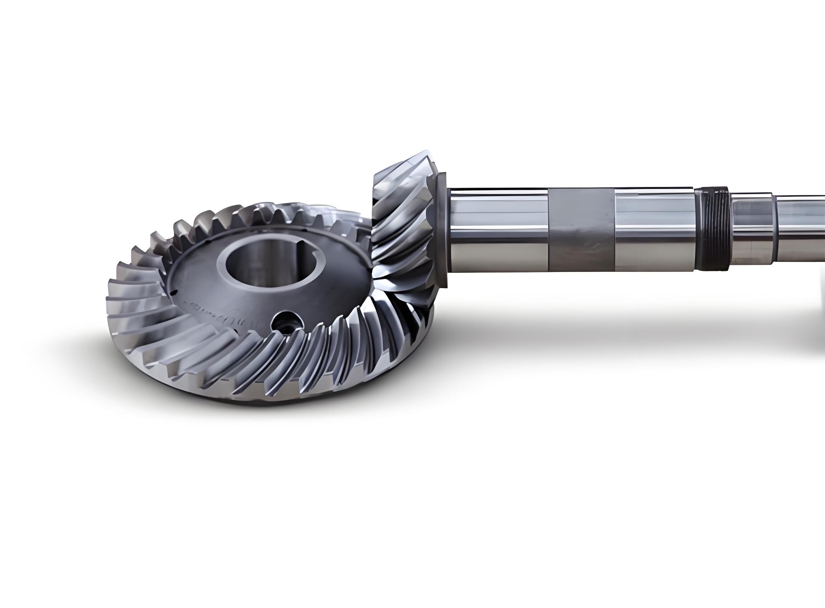
Virtual machining (VM) represents a mapping of the actual machining process within a digital environment. It leverages computer simulation and virtual reality technologies to realize a fully digital manufacturing process. This approach allows for the evaluation, prediction, and optimization of each stage of machining before physical production begins. Applying virtual machining technology to the design of spiral bevel gear cutting machines enables performance prediction during the design phase, leading to shortened development cycles, reduced costs, and the early detection of potential flaws in the machining process. This study focuses on establishing a virtual machine tool model and a corresponding simulation machining framework for spiral bevel gears, verifying its correctness through a complete digital machining cycle.
Machining Principle of Spiral Bevel Gears
The tooth cutting of spiral bevel gears is fundamentally based on the theory of the “second conjugate surface.” Given a first conjugate surface (the tool surface, representing the generating gear tooth surface) and the prescribed relative motion between this surface and the workpiece, the second conjugate surface (the desired workpiece gear tooth flank) can be deterministically generated. In practice, spiral bevel gears are typically manufactured according to the phantom gear principle. In traditional mechanical machines, a rotating cutter head is mounted eccentrically on a cradle. The oscillating motion of this cradle simulates the rotation of the imaginary generating gear (the phantom gear). As the cutter head rotates on its own axis, its cutting edges form a revolving surface. The workpiece and the imaginary generating gear rotate about their respective axes with a specific ratio (roll), causing the cutter edges to progressively sweep out the desired tooth form on the workpiece blank. The principle for machining using a phantom flat-top gear is conceptually illustrated in relevant technical literature.
The mathematical foundation lies in enforcing the conjugate condition between the generating surface $\Sigma_1$ and the workpiece surface $\Sigma_2$. This condition, often expressed through the equation of meshing, ensures continuous contact along a line. For a given cutter geometry and prescribed machine kinematics (relative motion), solving this condition yields the topography of the machined spiral bevel gear tooth flank.
Structural Evolution of Spiral Bevel Gear Machines
The traditional mechanical cradle-type machine has inherent limitations: complex structure, difficult setup, high inertia of the cradle limiting cutting speed, and consequently, lower productivity. Modern CNC spiral bevel gear generators, such as the Free-form type or Gleason’s PHOENIX®II series, have revolutionized the architecture. The Free-form type machine (conceptual diagram available in technical resources) replaces the physical cradle with digitally coordinated linear axes (typically X and Y) that control the center position of the cutter head in the machine plane, effectively simulating the cradle’s motion. The workpiece is mounted on a rotary axis (A) and a tilt axis (B) for rotation and root angle adjustment, respectively. A linear Z-axis provides the feed motion. This design eliminates the cradle and its associated worm drive, simplifying the structure, reducing inertia, enabling higher rotational speeds for the generating motion, and facilitating higher cutting speeds and efficiency.
While machines like the PHOENIX®II represent the pinnacle with features like monolithic column design for extreme stiffness and capability for dry cutting, they do not alter the underlying phantom gear machining principle. The core innovation is the replacement of mechanical cams and gears with digitally synchronized servo drives to execute the necessary relative motions. This research utilizes a virtual model based on the Free-form machine architecture for simulation purposes, as it encapsulates the core kinematic requirements for generating spiral bevel gears.
Simulation Machining Model for Spiral Bevel Gears
The essence of machining spiral bevel gears is to accurately realize the precise relative motion between the cutter head and the workpiece. For a Free-form type CNC machine, this involves determining the real-time position of its five controlled axes: the linear axes X, Y, Z and the rotary axes A, B. The required machining parameters fall into two main categories: cutter parameters and machine motion parameters.
Cutter Head Parameters
Cutter parameters are predetermined based on the gear design. The geometry and accuracy of the cutter head directly influence the final quality of the spiral bevel gears. The nominal cutter diameter $D_c$ is selected according to basic gear parameters like outer cone distance, face width, whole depth, spiral angle, and module. Other critical cutter parameters are then calculated.
A schematic of the cutter head shows its key features. For the gear member (e.g., the gear member in a pair), the main parameters are calculated as follows:
The point width (blade edge distance) on the gear cutter, $W_2$:
$$
W_2 = \frac{R_m}{R} \left( S_1 \cos \beta_m – 2 h_{f2}’ \tan \alpha \right)
$$
The outer blade point diameter, $D_{oe}$:
$$
D_{oe} = D_c + W_2
$$
The inner blade point diameter, $D_{ie}$:
$$
D_{ie} = D_c – W_2
$$
The pressure angles for the outer and inner blades, $\alpha_o$ and $\alpha_i$, are adjusted from the nominal pressure angle $\alpha$ by a small amount $\Delta \alpha$ which is a function of the cutter number $N$ (e.g., $\Delta \alpha = 10 \cdot N$ minutes of arc). Typically:
$$
\alpha_o = -(\alpha – \Delta \alpha), \quad \alpha_i = (\alpha + \Delta \alpha)
$$
Similar calculations are performed for the pinion cutter head. These parameters must be meticulously defined in the virtual machining environment.
Machine Kinematics and Coordinate Systems
To compute the machine motion parameters, a series of coordinate systems are established to describe the generation process virtually, even for a cradle-less machine. This kinematic chain defines the transformation from the workpiece to the machine base. Key coordinate systems typically include:
- $S_{m1}$: Machine fixed coordinate system.
- $S_{c1}$: “Cradle” coordinate system (virtual, representing the generating gear).
- $S_{t1}$: Cutter head coordinate system, defined by radial setting $S_t$ and angular setting $q_t$.
- $S_{a}$, $S_{f}$: Auxiliary coordinate systems for locating the workpiece, incorporating settings like sliding base ($X_{B1}$), vertical wheel offset ($V_{B1}$), axial wheel offset ($E_{B1}$), and machine root angle ($\gamma_{m1}$).
- $S_1$: Workpiece coordinate system, rotating about its axis with angular velocity $\omega^{(1)}$.
The fundamental requirement is that the virtual cradle (generating gear) and the workpiece rotate with angular velocities $\omega^{(c)}$ and $\omega^{(1)}$ satisfying a specific ratio (roll) that fulfills the equation of meshing. The core computational task is to transform the workpiece surface definition through this kinematic chain to the machine base, thereby solving for the time-dependent positions of the X, Y, Z, A, and B axes that will produce the correct relative motion. This involves successive coordinate transformations using homogeneous transformation matrices.
The motion of the virtual cradle is translated into the coordinated linear motion of the X and Y axes controlling the cutter center location ($\mathbf{C}(t) = [X(t), Y(t)]^T$), while the workpiece rotation $\phi_1(t)$ is executed by the A-axis. The B-axis sets the root angle, and the Z-axis provides feed $Z(t)$. The relationship is derived from the kinematic model:
$$
\mathbf{T}_{m1}^{tool}(t) = \mathbf{T}_{m1}^{cradle} \cdot \mathbf{T}_{cradle}^{cutter}(S_t, q_t) \quad \text{and} \quad \mathbf{T}_{m1}^{workpiece}(t) = \mathbf{T}_{m1}^{f} \cdot \mathbf{T}_{f}^{1}(\phi_1(t))
$$
Where $\mathbf{T}_{a}^{b}$ denotes the transformation from frame *a* to frame *b*. The condition that the cutter surface contacts the workpiece surface at the correct point leads to the equations defining $X(t)$, $Y(t)$, $\phi_1(t)$, etc.
Simulation Machining Case Study
A virtual machining platform was constructed using VERICUT software. A 3D model of a face milling cutter head was created, and a virtual Free-form type spiral bevel gear generator was assembled with its kinematic chain properly defined through a machine configuration file. A pair of spiral bevel gears with specified geometric parameters was modeled in a CAD system (e.g., Pro/ENGINEER) and imported into the VERICUT environment. The basic parameters for the gear pair are summarized in Table 1.
| Parameter | Pinion | Gear | Parameter | Pinion | Gear |
|---|---|---|---|---|---|
| Number of Teeth | 15 | 46 | Spiral Angle | 35° | |
| Module (mm) | 8.22 | Pitch Diameter (mm) | 123.30 | 378.12 | |
| Face Width (mm) | 57.15 | Pitch Angle | 18.06° | 71.94° | |
| Working Depth (mm) | 13.974 | Cone Distance (mm) | 198.86 | ||
| Whole Depth (mm) | 15.519 | Circular Pitch (mm) | 25.82 | ||
| Pressure Angle | 20° | Addendum (mm) | 9.85 | 4.12 | |
| Shaft Angle | 90° | Dedendum (mm) | 5.67 | 11.40 | |
Based on the gear design, the cutter parameters for the gear member were calculated. The results are listed in Table 2.
| Parameter | Value |
|---|---|
| Cutter Diameter, $D_c$ (mm) | 304.8 (12 inches) |
| Point Width, $W_2$ (mm) | 4.5 |
| Outer Blade Point Diameter, $D_{oe}$ (mm) | 309.3 |
| Inner Blade Point Diameter, $D_{ie}$ (mm) | 300.3 |
| Inner Blade Pressure Angle, $\alpha_i$ | 21° |
| Outer Blade Pressure Angle, $\alpha_o$ | -19° |
The machine motion parameters (axis positions as functions of time or rotational index) were computed offline using a dedicated algorithm (e.g., implemented in MATLAB) based on the kinematic model and gear geometry. These parameters were post-processed into NC code (G-code) recognizable by the virtual machine. A segment of the NC code for machining a single tooth flank of the gear, using circular interpolation for the generating motion, might appear as follows (illustrative snippet):
N0010 G40 G17 G94 G90
N0020 T0001 M06
N0030 G00 G54 X0 Y0 Z-50 M03 B=-21.3145
...
N0550 G01 X105.589498 Y-105.589498 C-48.383881 Z-50
N0560 G03 X107.416207 Y-103.730625 I-105.589498 J105.589498 C-49.435704 Z-50
N0570 G03 X109.210196 Y-101.840155 I-107.416207 J103.730625 C-50.487528 Z-50
...
N0800 G03 X140.320634 Y-51.072534 I-139.407924 J53.513688 C-74.679468 Z0
N02000 M02
In this code, X and Y coordinates control the cutter center path simulating cradle motion, C (or A) controls the workpiece rotation, B sets the root angle, and Z provides feed. The virtual machine model in VERICUT then executed this code. The material removal process was simulated in real-time, resulting in the digital manufacture of the gear and pinion tooth forms within the software. The successful generation of three-dimensional tooth geometries for both the pinion and the gear in the simulation, with correct tooth bearing and profile, validates the accuracy of the virtual machine model, the kinematic calculations, and the overall simulation machining process for spiral bevel gears.
Conclusion
This research demonstrates the application of virtual manufacturing technology to the domain of spiral bevel gear machining. By establishing a detailed kinematic model of a Free-form type spiral bevel gear generator and implementing it within a powerful simulation environment like VERICUT, a complete digital twin of the machining process was created. The methodology encompassed the calculation of essential cutter parameters, the derivation and computation of complex machine motion parameters based on the phantom gear principle, and the execution of these motions on a virtual machine tool model. The successful virtual machining of a conjugate spiral bevel gear pair, resulting in geometrically correct digital gear models, confirms the validity of the proposed virtual machine model and the simulation framework. This approach provides a powerful tool for the design, verification, and optimization of spiral bevel gear cutting processes, machine tool development, and NC program validation, thereby contributing to enhanced manufacturing precision and efficiency for these critical power transmission components.