
Introduction
With the rapid development of the automotive industry, the demand for differential gears is increasing, and the requirements for their transmission quality are also becoming higher and higher. Cold extrusion is an advanced manufacturing process that can greatly improve the comprehensive mechanical properties of gears and has obvious advantages. It has gradually been promoted in China. Due to its shape and structural characteristics, differential gears have become one of the most suitable objects for cold extrusion forming among gear products. Engineers and scholars at home and abroad have regarded cold extrusion forming technology as the first choice for the development of differential gears, greatly improving the development speed and production efficiency of differential gear cold extrusion parts. However, most scholars focus on the design of mold parameters based on the forming process and metal flow laws of gears, and rarely mention the manufacturing of gear cold extrusion molds. Currently, there are mainly two production processes for gear molds in the industry: electrical discharge machining and high-speed milling. Electrical discharge machining has low efficiency and spark patterns on the surface after discharge, which cannot be directly cold extruded and requires polishing treatment; high-speed milling has problems such as high material hardness, tool wear, and large tool allowance. This article focuses on the research of high-speed milling process for gear cold extrusion molds, and optimizes process parameters through finite element analysis, providing research ideas and demonstration cases for the high-speed milling of difficult-to-machine materials.
Difficulties and strategies of milling
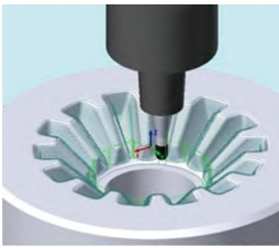
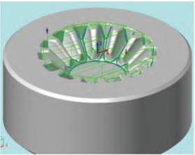
The gear mold material is DC53 die steel with a hardness of HRC62, and the tool wear and allowance are relatively large. If the processing accuracy is to reach the level indicator within the specified time, it is necessary to control the tool wear and ensure the continuity of the processing process. If single tooth processing is carried out, due to tool wear, it is difficult to ensure the consistency of the pitch in the direction of the gear mold tooth profile (circumference). Therefore, the gear mold needs to be processed in a circular manner and uses a constant height cutting method for semi-finishing and finishing, that is, a “circular constant height” cutting method. Since the cutting is carried out in the same direction, as the tool wear causes the workpiece undercut to accumulate at the bottom of the workpiece, an alternating cutting method is used to avoid the accumulation of allowance after tool wear. In the processing of high-hardness materials, once the tool is allowed to cut, it is difficult to return to its original state. During the processing process, there is a large amount of cutting allowance at the fillet position, which is more prone to allowance, so it is necessary to perform back gouging before constant height processing.
Reasonably planning the processing technology and setting parameters such as cutting amount and machining allowance are particularly important for controlling tool wear and allowance The cost of the traditional trial cutting method is high, and cutting tests can be conducted through finite element simulation to study the impact of cutting parameters on tool wear.
Establish cutting model for gear
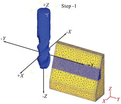
The workpiece is simplified as a bevel model, with the angle of the workpiece gear ranging from 60° to 80°. The bevel angle is set at 70°, and a Zhuzhou Diamond HMX-4B high-hardness four-edge straight shank ball end mill with a helical angle of 35° is selected. In order to improve the simulation effect, both the workpiece and the tool are locally refined. In addition to rotating around the axis, the tool also performs translational motion along the bevel, which is consistent with the cutting method of surrounding the same height.
Selecting spindle speed, milling depth, and feed rate as the main factors, a single-factor experiment was designed to observe the effect of cutting parameters on cutting force and tool wear. The cutting method during the processing of this mold is circumferential contouring, and the cutting force in the X direction is normal cutting force, which causes the center of the tool to be far away from the cutting surface, resulting in actual cutting depth being less than theoretical cutting depth, leading to tool feed. The cutting force in the Y direction is tangential cutting force, which has little effect on the amount of tool feed. Therefore, the two factors that have a greater impact on the amount of tool feed are the cutting force in the X direction and tool wear. The single-factor experimental design and results indicate that the root mean square of the cutting force is used, and the mold milling process is semi-finishing and finishing. The milling depth in the simulation is relatively small.
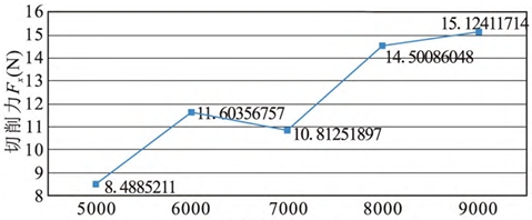
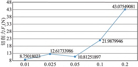
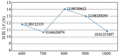
With the increase in spindle speed, the cutting force shows a slow increase trend, indicating that in finishing with a small cutting depth, the spindle speed has little effect on the cutting force. It is the effect of milling depth on the cutting force. It can be seen that when the cutting depth is ≤0.05mm, the cutting force changes little; when the cutting depth is >0.05mm, the cutting force increases significantly as the cutting depth increases. The effect of feed rate on the cutting force, within the experimental range, when the cutting depth is 0.05mm, the feed rate has little effect on the cutting force.
The influence of cutting parameters on tool wear. The influence of spindle speed on tool wear can be seen that, within the experimental range, as the spindle speed increases, tool wear first decreases and then increases. The influence of milling depth on tool wear can be seen that, when the cutting depth is ≤0.05mm, the tool wear changes little and the value is small; when the cutting depth is >0.05mm, as the cutting depth increases, the tool wear increases significantly. This is basically consistent with the influence of milling depth on cutting force. Figure 5c shows the influence of feed rate on tool wear. It can be seen that, within the experimental range, when the cutting depth is 0.05mm and the feed rate is ≤800mm/min, the feed rate decreases and the tool wear increases; when the feed rate is >800mm/min, the tool wear is small and changes little.
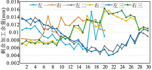
The three-coordinate measuring machine is used for measurement, and this equipment has a dedicated gear detection module that can be tested according to the DIN3965 standard. The gear mold has been measured to meet the Level 1 level of the DIN3965 standard, with a roughness detection result of Ra < 0.26μm, and subsequent testing is no longer required Polishing, can be directly used for product extrusion.
Epilogue
By optimizing the process plan through finite element analysis and other methods, the problems of high material hardness and poor surface quality during the milling process of automotive differential gear molds were solved The following conclusions were drawn regarding issues such as tool wear and the amount of tool damage.
(1) When milling difficult-to-machine materials, it is important to set the cutting parameters reasonably, and finite element analysis methods can provide a basis for this.
(2) When milling at high speed, the factor that has the greatest impact on cutting force and tool wear is the milling depth. When the milling depth is small, the cutting force The change in tool wear is not significant and the value is small; when the milling depth reaches a certain value, the cutting force and tool wear increase with the increase of milling depth Both increased significantly, and the change trend was basically the same.
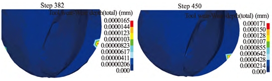
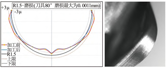
(3) The main wear position of the ball-end milling cutter is the part that is in contact with the workpiece more, which is related to the angle of the workpiece. In high-speed finishing of the DC53 mold, the part that is in contact with the workpiece is the most worn When the steel is used, both the front and rear cutting surfaces are worn.
(4) When milling materials with high hardness, it is reasonable to use old tools. The method in this article can provide a reference for the number of times the tool is used.