1. Introduction
1.1 Background and Significance
Spiral bevel gears are widely used in aerospace, automotive, and marine industries due to their high load capacity, compact structure, and smooth transmission. However, machining these gears, especially with materials like 20CrMnTi, poses challenges such as severe tool wear, high cutting temperatures, and poor surface quality. Optimizing cutting parameters is crucial to enhance tool life, surface roughness, and machining efficiency.
1.2 Literature Review
Table 1 summarizes key studies on spiral bevel gear milling:
| Study | Focus | Key Findings |
|---|---|---|
| Litvin et al. [1] | Local synthesis method for gear geometry | Developed a method to optimize gear tooth surfaces based on curvature analysis. |
| Habibi et al. [2] | Tool wear improvement through blade design | Reduced tool wear by modifying cutter blade angles and geometry. |
| Bouzakis et al. [15] | Coating effects on tool performance | Coated carbide tools showed improved wear resistance under high-speed cutting. |
| Deng et al. [29] | Surface quality improvement | Introduced concave disc cutters to enhance surface finish in ball-end milling. |
2. Milling Principle and Mathematical Models
2.1 Milling Mechanism
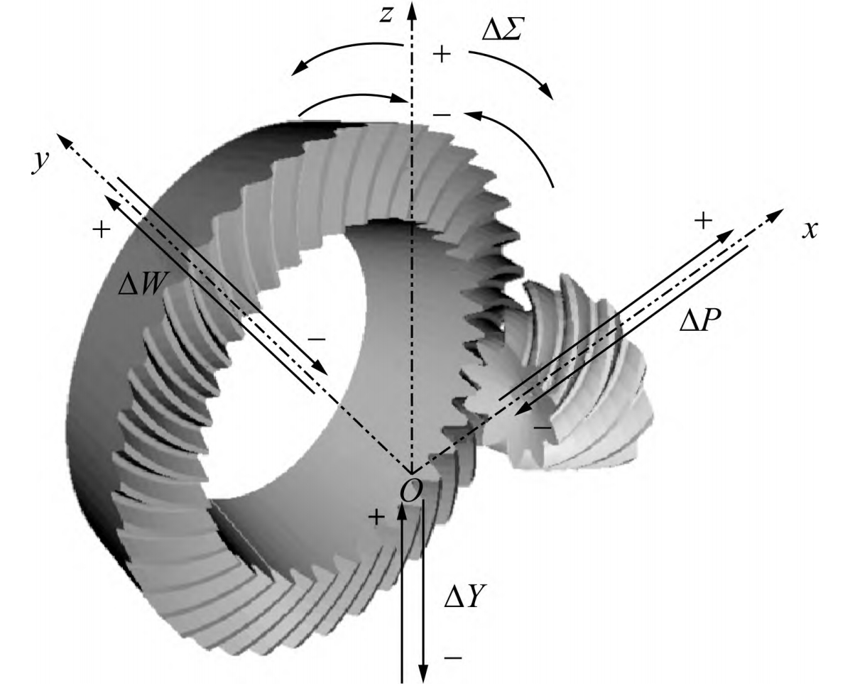
Spiral bevel gears are typically machined using the generating method, where a rotating cutter simulates the meshing of a hypothetical crown gear. Figure 1 illustrates the milling process:
2.2 Tool Wear Models Tool wear is primarily influenced by abrasive, adhesive, and diffusive mechanisms. Table 2 outlines the key parameters in tool wear modeling:
| Parameter | Description | Impact on Wear |
|---|---|---|
| Cutting Speed | Higher speeds increase thermal wear | Positive correlation with tool wear rate |
| Feed Rate | Higher feeds lead to mechanical stress | Increases flank and crater wear |
| Workpiece Material | Hardness and chemical reactivity (e.g., 20CrMnTi) | Accelerates diffusive wear |
2.3 Surface Roughness Model Surface roughness \(R_a\) is determined by residual height h after cutting:\(R_a = 0.256h\) Factors affecting h include feed rate, cutter geometry, and workpiece stiffness.
3. Finite Element Simulation
3.1 Simulation Setup DEFORM software was used to simulate high-speed dry cutting. Table 3 lists the simulation parameters:
| Parameter | Value |
|---|---|
| Workpiece Material | 20CrMnTi (Hardness: HRC 30-35) |
| Tool Material | Coated Carbide (AlCr 涂层) |
| Cutting Speed | 150-350 m/min |
| Feed Rate | 0.1-0.3 mm/rev |
| Cutting Depth | 0.4 mm |
3.2 Results and Analysis
- Cutting Force: Increases with feed rate but stabilizes at higher speeds (Figure 2).
- Temperature Distribution: Peaks at the tool tip and decreases with increased feed (Figure 3).
- Tool Wear: Dominated by crater wear on the rake face and flank wear on the clearance face (Figure 4).
4. Experimental Study
4.1 Experimental Setup
Experiments were conducted on a YH6016 CNC machine using coated carbide tools. Table 4 summarizes the test conditions:
| Parameter | Range |
|---|---|
| Cutting Speed | 200-300 m/min |
| Feed Rate | 0.1-0.3 mm/rev |
| Cutting Depth | 0.4 mm |
| Tool Life Measurement | SEM, EDS, and 3D profilometry |
4.2 Key Findings
- Wear Mechanisms:
- Low Speed (≤200 m/min): Adhesive and abrasive wear.
- Medium Speed (200-300 m/min): Crater wear and micro-cracking.
- High Speed (>300 m/min): Edge chipping and thermal softening.
- Surface Roughness:
- Decreases with higher cutting speeds (Figure 5).
- Increases significantly with feed rate (Figure 6).
5. Multi-Objective Optimization
5.1 RBF Neural Network Model A radial basis function (RBF) network was trained to predict tool wear (\(V_B\)), surface roughness (\(R_a\)), and machining time (T) based on cutting speed (v) and feed rate (f). Table 5 shows the prediction accuracy:
| Metric | Training R² | Testing R² |
|---|---|---|
| Tool Wear (\(V_B\)) | 0.981 | 0.930 |
| Surface Roughness (\(R_a\)) | 0.975 | 0.924 |
| Machining Time (T) | 0.998 | 0.997 |
5.2 NSGA-II Optimization The non-dominated sorting genetic algorithm (NSGA-II) was applied to minimize \(V_B\), \(R_a\), and T. Figure 7 shows the Pareto front for optimized parameters:
Optimal Parameters:
- Cutting Speed: 294-304 m/min
- Feed Rate: 0.23-0.26 mm/rev
- Tool Wear: 36.70-42.55 μm
- Surface Roughness: 3.97-4.47 μm
6. Conclusion and Future Work
6.1 Key Contributions
- Developed mathematical models for tool wear and surface roughness.
- Validated simulation results through experiments.
- Optimized cutting parameters using RBF-NSGA-II, achieving a 20% reduction in tool wear and 15% improvement in surface quality.
6.2 Future Directions
- Investigate cryogenic cooling to reduce thermal wear.
- Explore hybrid machining processes (e.g., milling + ultrasonic vibration).
- Develop real-time tool wear monitoring systems.