1. Introduction
1.1 Research Background and Significance
In mechanical transmission systems, gear transmission is highly efficient and can transmit large torques. Spiral bevel gears, a special type of bevel gear, are widely used in various industries such as automotive, aerospace, and shipbuilding. They are known for their compact structure, strong bearing capacity, high coincidence degree, and smooth transmission with low noise. For example, in helicopter tail – wing transmission systems and automotive transmission systems, spiral bevel gears play a crucial role, as shown in Figure 1 – Helicopter Tail – Wing Transmission Shaft and Figure 2 – Ford Automobile Transmission Structure.
[Insert Figure 1 – Helicopter Tail – Wing Transmission Shaft: A clear image of a helicopter tail – wing transmission shaft with spiral bevel gears clearly visible. Highlight the gears and their connection to the shaft.] [Insert Figure 2 – Ford Automobile Transmission Structure: A diagram or photo of a Ford automobile transmission structure, with spiral bevel gears marked and emphasized.]
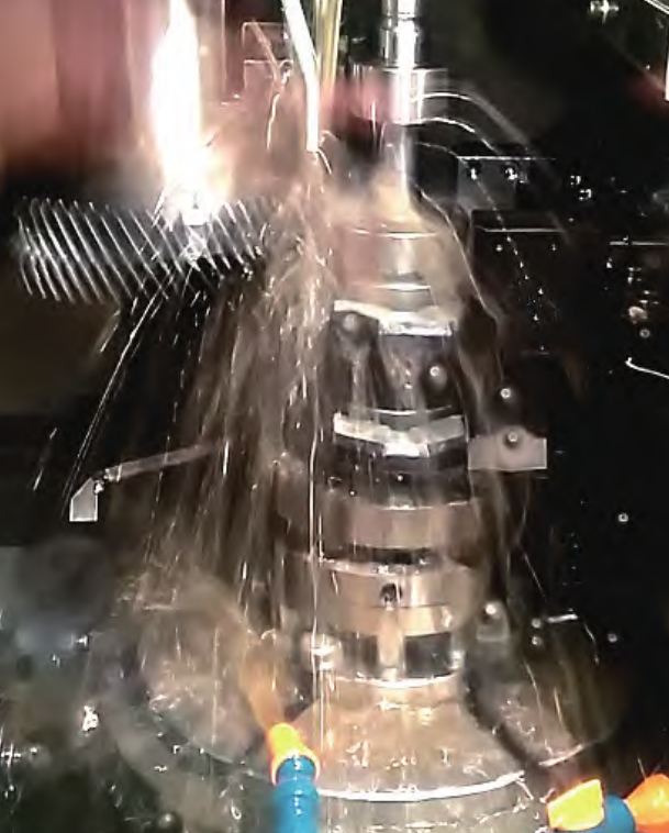
The position and shape of the tooth – surface contact area in spiral bevel gear transmission are important references for evaluating the transmission accuracy and performance of meshing gear pairs. Currently, in China, spiral bevel gears are mainly processed using traditional single – and double – sided internal and external cutters. However, during the cutting process, the tool gradually wears, which is affected by factors such as the mechanical properties of the tool and workpiece materials, cutting parameters, cooling conditions, cutting force, and cutting temperature. The main causes of tool wear are physical impact and chemical reactions. The selection of cutting parameters can significantly influence the actual surface quality of spiral bevel gears. Therefore, it is necessary to study the influence of cutting parameters on tool wear and the surface roughness of the workpiece. By optimizing the cutting parameters using algorithms like the RBF neural network – NSGA genetic algorithm, we can achieve the goals of minimizing tool wear and surface roughness, and improve the processing efficiency.
1.2 Research Status at Home and Abroad
1.2.1 Research Status of Milling Principle of Spiral Bevel Gears at Home and Abroad
The geometric relationship of spiral bevel gear transmission was initially proposed by Wildhaber, Baxter, etc. Subsequently, Baxter analyzed the impact of installation errors of spiral bevel gears on gear operation. Based on the previous theoretical foundation, Swiss Oerlikon Company and German Klingelnberg Company have developed their unique processing technologies for spiral bevel gears and established relevant standards. Since the middle of the last century, Gleason Company has gradually formed a complete set of traditional design and processing technologies for spiral bevel gears. Traditional processing machine tools for spiral bevel gears mainly include three types: Gleason, Klingelnberg, and Oerlikon machine tools. Gleason Company uses circular – arc tooth systems, while Oerlikon and Klingelnberg companies use extended epicycloid tooth systems.
Litvin et al. independently proposed a local synthesis method. Habibi et al. established mathematical expressions for the cutting edge, rake angle, and clearance angle of spiral bevel gear milling cutters. Alfonso et al. proposed a new method for designing face – milled spiral bevel gear drives. Mu et al. proposed a tooth – surface modification method based on cutter – blade profile correction. Samani et al. proposed a new tooth – surface modification method with high – order transmission error. Wang et al. proposed a new adaptive geometric meshing theory. Yavuz et al. proposed a dynamic model including flexible components such as shafts and bearings. Zhao et al. proved the feasibility of precision plastic forming technology for manufacturing spiral bevel gears. You Chenglin proposed a new global optimization algorithm for solving the problem of non – equidistant discrete curves in the generation of spiral bevel gears by face – milling in simulation software.
In China, before the 1980s, Gleason manufacturing technology was used to process spiral bevel gears. Due to technical limitations, the actual meshing performance of the manufactured spiral bevel gears was poor, and the processing efficiency was low. To solve these problems, Wu Daren’s team from Nankai University and Professor Chen Zhixin from Shanghai University of Technology derived the induced normal curvature formula of conjugate surfaces. Wang Lei et al. studied the tooth – surface modification technology based on the processing center of spiral bevel gears. Liu Guanglei et al. actively designed the meshing trace direction angle of spiral bevel gears. Deng Jing et al. verified the relationship between the residual height of spiral bevel gear processing and cutting parameters through experiments. Cao Xuemei et al. proposed a decomposition algorithm for gear contact analysis. A summary of these studies is shown in Table 1.
| Researcher(s) | Research Content |
|---|---|
| Wildhaber, Baxter | Proposed the geometric relationship of spiral bevel gear transmission |
| Baxter | Analyzed the impact of installation errors on gear operation |
| Oerlikon, Klingelnberg | Developed unique processing technologies and standards |
| Gleason | Formed traditional design and processing technologies |
| Litvin et al. | Proposed a local synthesis method |
| Habibi et al. | Established cutter – related mathematical expressions |
| Alfonso et al. | Proposed a new design method for face – milled spiral bevel gear drives |
| Mu et al. | Proposed a tooth – surface modification method |
| Samani et al. | Proposed a new tooth – surface modification method with high – order transmission error |
| Wang et al. | Proposed an adaptive geometric meshing theory |
| Yavuz et al. | Proposed a dynamic model with flexible components |
| Zhao et al. | Proved the feasibility of precision plastic forming technology |
| You Chenglin | Proposed a new global optimization algorithm |
| Wu Daren, Chen Zhixin | Derived the induced normal curvature formula |
| Wang Lei et al. | Studied tooth – surface modification technology |
| Liu Guanglei et al. | Actively designed the meshing trace direction angle |
| Deng Jing et al. | Verified the relationship between residual height and cutting parameters |
| Cao Xuemei et al. | Proposed a decomposition algorithm for gear contact analysis |
Table 1 – Research Status of Milling Principle of Spiral Bevel Gears
However, the research on tool wear and workpiece surface roughness during the face – milling process of spiral bevel gears is relatively scarce.
1.2.2 Research Status of Tool Wear in Spiral Bevel Gear Processing at Home and Abroad
Spiral bevel gears and hypoid gears are widely used in the automotive, shipbuilding, and aerospace industries. Research on tool wear mainly focuses on the wear mechanism and characteristics of single – and double – sided milling cutters. Stachurski discussed the influence of tool geometry and cutting parameters on tool wear and tool life. Bouzakis et al. explored the cutting process of two – axis milling of bevel gears and analyzed the influence of coating tools’ surface preparation and geometry on tool life. Stadtfeld et al. proposed a new 双刃 tool design. Klocke et al. further studied traditional carbide tools for processing spiral bevel gears and proposed a new WZL face – milling cutter concept. Liu et al. studied the influence of tool parameters on cutting force in the dry high – speed cutting process of 20CrMnTi spiral bevel gears and hypoid gears.
In China, scholars mainly focus on the analysis of cutting temperature, tool geometry, and tool wear principles of spiral bevel gear processing tools. Wei Wei et al. proposed a tool structure with a negative land. Gao Niping proposed a design method for electrochemical machining cathode tools. Wen Wu et al. studied the tool wear mechanism of carbide tools in processing 20CrMnTi carburized and quenched steel. Liao Congjian studied the cutting force of bevel gears and established a cutting – force model. The details are presented in Table 2.
| Researcher(s) | Research Content |
|---|---|
| Stachurski | Discussed the influence of tool geometry and cutting parameters on tool wear and life |
| Bouzakis et al. | Explored the cutting process and analyzed the influence of coating tools |
| Stadtfeld et al. | Proposed a new 双刃 tool design |
| Klocke et al. | Studied traditional carbide tools and proposed a new cutter concept |
| Liu et al. | Studied the influence of tool parameters on cutting force |
| Wei Wei et al. | Proposed a tool structure with a negative land |
| Gao Niping | Proposed a design method for electrochemical machining cathode tools |
| Wen Wu et al. | Studied the tool wear mechanism of carbide tools |
| Liao Congjian | Studied the cutting force of bevel gears and established a model |
Table 2 – Research Status of Tool Wear in Spiral Bevel Gear Processing
However, the research on the influence of cutting parameters on tool wear is relatively insufficient.
1.2.3 Research Status of Milling Processing Surface Quality of Spiral Bevel Gears at Home and Abroad
The main factors affecting the surface quality of processed spiral bevel gears include cutting force, cutting heat, cutting parameters, and residual stress. Currently, due to the interaction of these factors, it is only possible to obtain the influence degree of surface roughness by controlling single – factor variables. Domestic and foreign scholars have established various roughness mathematical models to verify the quantitative relationship between processing surface roughness and cutting parameters. Du et al. conducted cutting simulation analysis and processing to improve the surface quality of spiral bevel gears. Deng et al. proposed a new face – milling method. Zheng et al. revealed the influence of design and process parameters on surface roughness distribution. Ghani et al. studied the influence of cutting parameters on surface roughness when using coated carbide tools. Yang Zhenchao et al. analyzed the surface morphology of TC4 under different milling speeds. Liu et al. studied the influence of workpiece hardness on surface roughness. Table 3 summarizes these studies.
| Researcher(s) | Research Content |
|---|---|
| Various scholars | Established roughness mathematical models |
| Du et al. | Conducted cutting simulation and processing to improve surface quality |
| Deng et al. | Proposed a new face – milling method |
| Zheng et al. | Revealed the influence of parameters on surface roughness distribution |
| Ghani et al. | Studied the influence of cutting parameters on surface roughness with coated tools |
| Yang Zhenchao et al. | Analyzed the surface morphology of TC4 under different milling speeds |
| Liu et al. | Studied the influence of workpiece hardness on surface roughness |
Table 3 – Research Status of Milling Processing Surface Quality of Spiral Bevel Gears
However, there are few studies on improving the surface quality of spiral bevel gear processing through parameter optimization algorithms.
1.2.4 Research Status of Cutting Parameter Optimization for Spiral Bevel Gear Milling at Home and Abroad
The selection of cutting parameters in the face – milling process of spiral bevel gears can affect many factors. Domestic and foreign scholars have conducted relevant research, mainly from aspects such as temperature, tool life, cutting force, and surface quality. Yilmaz et al. proposed the concept of a cumulative factor to obtain the relationship between cutting force and cutting parameters. Tseng et al. used an artificial neural network to establish a burr mathematical model. Altan et al. studied the influence of spindle speed on surface roughness. Zerti et al. explored the influence of cutting parameters on tool wear. Aramesh et al. studied the remaining useful life of tools. Kayabasi et al. determined the prediction model of surface roughness using an artificial neural network. In China, Dong Huiting et al. studied tool wear state monitoring based on tool temperature. Jia Xinjie proposed a cutting – parameter optimization scheme. These studies are presented in Table 4.
| Researcher(s) | Research Content |
|---|---|
| Yilmaz et al. | Proposed a cumulative factor to obtain the relationship between cutting force and parameters |
| Tseng et al. | Used an artificial neural network to establish a burr model |
| Altan et al. | Studied the influence of spindle speed on surface roughness |
| Zerti et al. | Explored the influence of cutting parameters on tool wear |
| Aramesh et al. | Studied the remaining useful life of tools |
| Kayabasi et al. | Determined the surface roughness prediction model using an artificial neural network |
| Dong Huiting et al. | Studied tool wear state monitoring based on tool temperature |
| Jia Xinjie | Proposed a cutting – parameter optimization scheme |
Table 4 – Research Status of Cutting Parameter Optimization for Spiral Bevel Gear Milling
Most of these studies focus on single – factor optimization, and there is a lack of research on multi – objective optimization of cutting parameters.
1.3 Research Sources and Main Content
1.3.1 Research Sources
This research project comes from the horizontal project “Harbin University of Science and Technology – Yancheng Hali Power Transmission and Intelligent Equipment Research Project” through school – enterprise cooperation.
1.3.2 Main Research Content
This paper focuses on the research of tool wear forms, mechanisms, and the surface roughness of processed workpieces in the processing of spiral bevel gears. The main research contents are as follows:
- Analyze the milling principle of spiral bevel gears based on the generation method, clarify the cutting trajectory of the tool, and theoretically derive the concave and convex tooth – surface equations of spiral bevel gears. Establish the tool wear model and the surface roughness model by analyzing the cutting trajectory and the surface residual height.
- Conduct finite – element simulation analysis of face – milling spiral bevel gears. Use CATIA software to build simulation models of processing tools and workpieces, and use DEFORM simulation software to simulate the influence of different cutting parameters on tool wear and workpiece surface strain under high – speed dry – cutting conditions.
- Carry out cutting – processing experiments of spiral bevel gears by face – milling. Use an ultra – depth – of – field microscope, scanning electron microscope, and energy spectrometer to detect tool wear, and analyze the wear forms and mechanisms under different cutting parameters. Use a P40 rolling inspection machine to detect the surface roughness of workpieces.
- Optimize the cutting parameters of spiral bevel gears using the NSGA – II genetic algorithm based on the RBF neural network approximation model. Select feed rate and cutting speed as inputs, and minimum tool wear, minimum surface roughness, and maximum processing efficiency as outputs to obtain the optimal cutting parameters.
2. Milling Principle and Mathematical Model Establishment of Spiral Bevel Gears
2.1 Milling Principle and Motion Analysis of Spiral Bevel Gears
2.1.1 Milling Principle of Spiral Bevel Gears
Spiral bevel gears can be processed by two methods: the generation method and the forming method. Both are intermittent cutting processes. In the generation method, the tooth profile of the processed gear is involute. During processing, the cutter head envelopes and cuts from the tooth tip to the tooth root. The inner and outer cutters of the cutter head machine the concave and convex tooth surfaces of the spiral bevel gear respectively. This process can be regarded as the meshing of a pair of spiral bevel gears, as shown in Figure 3 – Cutting Method of Spiral Bevel Gear (a). In the forming method, when processing each tooth groove, the workpiece needs to be in a stable state. The cutter head rotates and moves axially. After processing a single tooth groove of the gear blank, the gear blank rotates a specific angle for re – meshing and cutting, as shown in Figure 3 – Cutting Method of Spiral Bevel Gear (b). This method is suitable for mass production with high productivity. This paper mainly focuses on the generation – method processing of spiral bevel gears.
The generation – method processing of spiral bevel gears can be regarded as the process in which the cutting – edge trajectory forms a hypothetical flat – top gear meshing with the spiral bevel gear, that is, a hypothetical planar generating gear. The meshing principle of the hypothetical planar generating gear is shown in Figure 4 – Principle of Hypothetical Planar Gear Engagement. The main cutting edges of the outer and inner cutter strips of the high – speed – rotating cutter head form the concave and convex tooth surfaces of the hypothetical planar generating gear respectively. The tooth surface shows an extended epicycloid in the tooth – length direction and a straight line in the tooth – profile direction. The processed tooth surface of the spiral bevel gear is enveloped by the planar generating gear and is involute in the tooth – profile direction. The rolling ratio of the cutter to the workpiece is the transmission ratio of the two – gear meshing, which can be expressed as \(i_{g}=\frac{\cos\alpha_{g}}{\sin\beta_{g}}\), where \(\alpha_{g}\) and \(\beta_{g}\) are the rotation angles of the processed spiral bevel gear and the machine tool cradle respectively.
2.1.2 Motion Analysis of Milling Processing
The coordinate system for the generation – method processing of spiral bevel gears is shown in Figure 5 – Spiral Bevel Gear Machining Coordinate System. The cutter – head processing coordinate is in area A, with the z – axis coinciding with the cutter – head spindle. The \(y_{2}\) and \(x_{2}\) axes can be obtained by rotating the initial cutter – head axes \(y_{1}\) and \(x_{1}\). Area B is the coordinate system of the processed spiral bevel gear, with the origin \(O_{4}\). The processed spiral bevel gear rotates around the \(x_{4}\) axis. The origin of the machine – tool coordinate system is \(O_{2}\). The machine tool can move along the z – axis and rotate around the y – axis to adjust the positioning relationship between the processed spiral bevel gear and the cutter head.
3. Simulation and Result Analysis of Face – Milling Spiral Bevel Gears
3.1 Finite – Element Simulation Theory
DEFORM finite – element simulation software can discretize some problems that are difficult to solve accurately, making the solution more precise. The software mainly consists of three parts: pre – processing, calculation, and post – processing. The pre – processing module is used to set up the simulation environment, including importing 3D models, setting degrees of freedom, and defining contact relationships and friction coefficients. The calculation module solves the pre – processed model. The post – processing module can display the cutting force, stress, strain, and cutting temperature obtained during the solution process in the form of curves. During the simulation process, there is a thermo – mechanical coupling phenomenon of large strain rate and plastic deformation, which may cause the calculation result to change suddenly. In the metal – cutting field, there are mainly three methods: the Euler method, the Lagrangian method, and the Arbitrary Lagrangian – Eulerian (ALE) method. The ALE method is a compromise between the Euler and Lagrangian descriptions. The mesh can deform but does not completely move with the particles, ensuring that the simulation does not terminate due to element distortion and maintaining the contact between the chip and the workpiece. The simulation process of processing spiral bevel gears is a non – free – cutting and complex forming process, so the finite – element control equation \(\sum \int_{v_{0}} B^{T} S d V_{o}=\sum \int_{v_{0}} N^{T} f_{i o} d V_{o}=\sum \int_{A_{0}} N^{T} F_{i o} d A_{o}\) is adopted, where \(F_{\bar{i}}\) is the unit – volume surface – stress load vector, \(f_{i}\) is the unit – volume force – load vector, A and V are the volume and surface – volume in the actual configuration, N is the unit – shape function, and B is the unit – strain matrix.