
In the field of heavy machinery, the rack and pinion gear drive stands out due to its straightforward construction and direct power transmission. My research focuses on the critical aspects of designing and analyzing heavy-duty rack and pinion systems, particularly those with large modules employed in demanding applications like mining excavators, marine lifting equipment, and other massive industrial machinery. The failure of these components, especially tooth breakage, can lead to catastrophic operational downtime and economic loss. Therefore, enhancing bending strength is paramount. Current design practices for such large-module rack and pinion gears often lack standardized reference codes or mature dedicated software, forcing reliance on iterative finite element analysis (FEA). This study aims to develop a systematic methodology for tooth profile optimization and a corresponding rapid analytical calculation method for root stress, thereby streamlining the initial design phase for heavy-duty rack and pinion gear sets.
The fundamental challenge in designing these rack and pinion systems lies in balancing strength, wear resistance, and manufacturability. For open gearing in harsh environments, the primary failure modes are tooth breakage from bending fatigue and excessive wear. Traditional standard gear profiles are not always optimal. This investigation delves into the influence of various tooth profile parameters on root stress and durability, establishing design formulas and a simplified computational framework for root stress assessment specific to large-module rack and pinion gears.
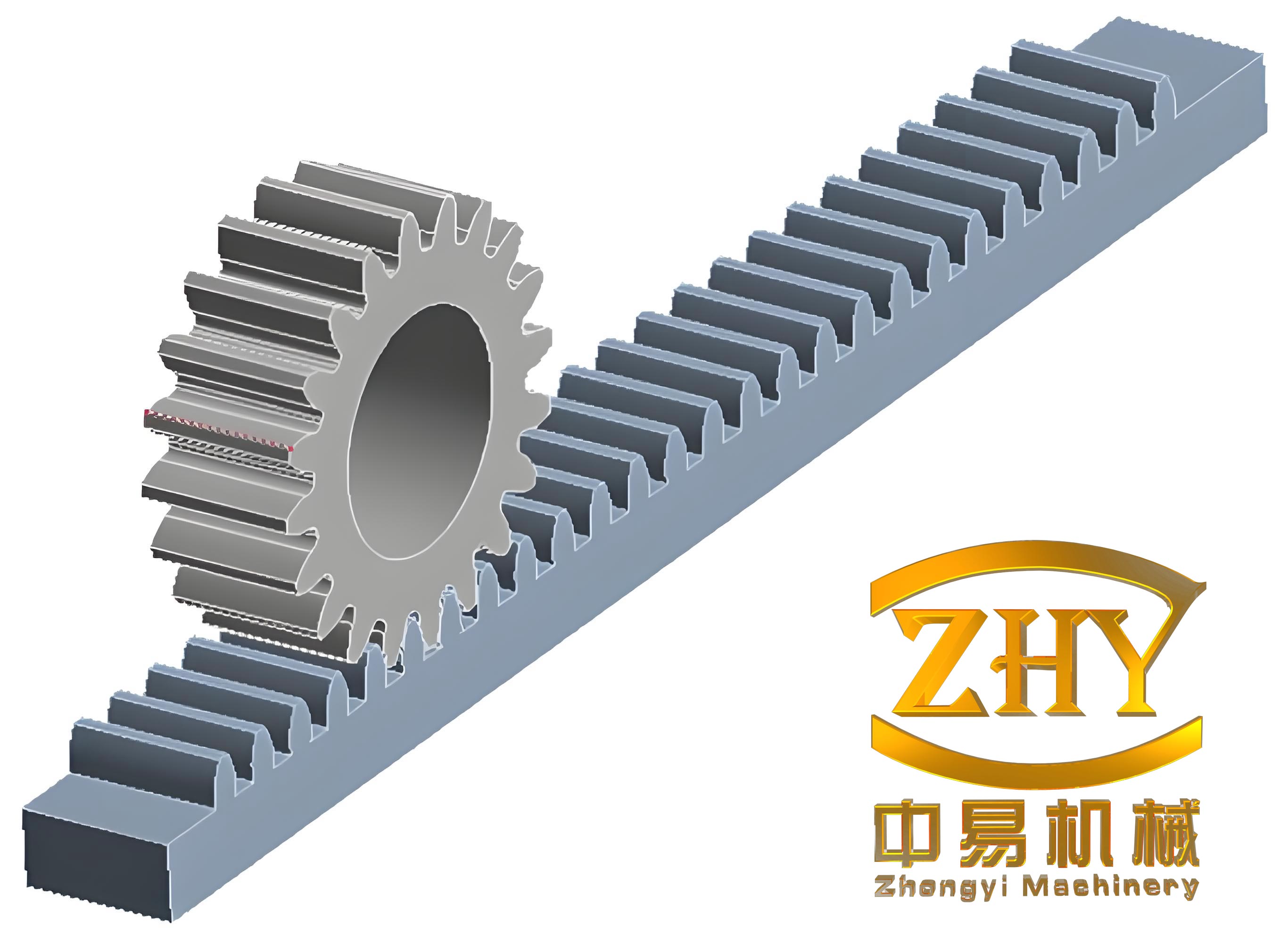
Designing the tooth profile for a heavy-duty rack and pinion gear set requires careful consideration of several interdependent parameters. Unlike standard gears produced by hobbing or shaping, these large components are often machined via milling for the pinion and crafted through CNC cutting or casting for the rack. The goal is to define a profile that maximizes the root fillet radius—to reduce stress concentration—without causing interference during meshing, while also ensuring sufficient tooth top land for wear resistance and adequate contact ratio for smooth operation.
The tooth top land (Sa) is crucial for wear resistance in open gear drives. For rack and pinion gears subjected to dynamic fatigue loads, a substantial top land is recommended. Conversely, for rack and pinion systems primarily under static loads, such as those in jack-up platforms, a smaller top land is acceptable. The calculation involves the pinion’s geometry:
$$S_a = d_a \left( \frac{\pi}{Z} + \text{inv} \, \alpha – \text{inv} \, \alpha_a \right)$$
$$\cos \alpha_a = \frac{d_b}{d_a}$$
where \(d_a\) is the tip diameter, \(\alpha_a\) is the tip pressure angle, \(Z\) is the number of pinion teeth, \(\alpha\) is the reference pressure angle, and \(d_b\) is the base circle diameter. The design must also satisfy the contact ratio (ε) requirement. A higher contact ratio minimizes impact loads and is vital for dynamically loaded rack and pinion gears. For static-load rack and pinion applications, a lower limit suffices due to typically higher pressure angles which otherwise would make the tooth tip too sharp.
$$\epsilon = \frac{Z_1 (\tan \alpha_{a1} – \tan \alpha)}{2\pi} + \frac{2h_{a2}’}{\pi m \sin 2\alpha}$$
Here, \(h_{a2}’\) represents the effective addendum height of the rack above the meshing point (see derivation below). The selection of profile shift coefficients (\(X\)) follows an equal-strength principle between the rack and pinion. A positive shift for the pinion increases its tooth thickness and strength, but correspondingly reduces the rack’s tooth thickness at the meshing region. Backlash (\(j_n\)) is another critical parameter for rack and pinion sets, accounting for manufacturing errors, thermal expansion, and mounting inaccuracies. It is typically set between 0.12m and 0.15m and is achieved by uniformly thinning the tooth thickness of both members.
The root fillet design is central to bending strength. A single large-radius fillet is preferable for the pinion to minimize root stress. The maximum feasible fillet radius (\(r_\rho\)) is determined by the lowest point of single-tooth contact on the pinion’s involute profile, which is usually slightly above the base circle. The formula for the pinion’s root fillet radius is:
$$r_\rho = \frac{D_b \left[ \tan(\alpha_{ce} + \text{inv} \, \alpha_{ce} + \frac{\pi}{Z} – \frac{S_{min}}{D} – \text{inv} \, \alpha) – \tan \alpha_{ce} \right]}{2}$$
$$\alpha_{ce} = \arccos\left( \frac{D_b}{D_{ce}} \right)$$
where \(D_{ce}\) is the diameter at the tangency point between the fillet and the involute (typically \(D_b + 2 \text{ to } 3 \text{ mm}\)), \(S_{min}\) is the actual tooth thickness at the reference diameter \(D\), and other symbols are as previously defined. For the rack in a rack and pinion system, the root can often utilize a double-radius fillet to reduce the rack’s dedendum height, thereby increasing the base thickness of the rack body and reducing overall deflection. The effective addendum height of the rack (\(h_{a2e}\)) is derived from the meshing geometry:
$$h_{a2}’ = r_a – r_{ce} \cdot \cos(\alpha – \alpha_{ce})$$
$$h_{a2e} = h_{a2}’ + X m$$
where \(r_a\) is the pinion tip radius and \(r_{ce}\) is the radius at the tangency point \(D_{ce}/2\). The total rack tooth height (\(h_{a2}\)) is then \(h_{a2} = h_{f1} – c^*\), with \(h_{f1}\) being the pinion dedendum and \(c^*\) the bottom clearance (often 10–12 mm for lubrication in open rack and pinion gears).
A summary of key design parameters and their typical ranges or calculation bases for heavy-duty rack and pinion gears is provided in the table below.
| Parameter | Symbol | Consideration for Rack and Pinion Gears | Typical Range/Formula |
|---|---|---|---|
| Tooth Top Land (Pinion) | \(S_a\) | Wear resistance; differs for fatigue vs. static load. | Fatigue: \(S_a \geq 0.4m\); Static: \(S_a \geq 0.15m\) |
| Contact Ratio | \(\epsilon\) | Smoothness, load sharing. | Fatigue: \(\epsilon \geq 1.2\); Static: \(\epsilon \geq 1.05\) |
| Backlash | \(j_n\) | Compensate for errors and thermal expansion. | \(j_n = (0.12 \text{ to } 0.15)m\) |
| Pinion Root Fillet Radius | \(r_\rho\) | Maximize to reduce bending stress. | Calculated via Eq. (4) & (5). |
| Profile Shift Coefficient (Pinion) | \(X\) | Equal strength principle for the rack and pinion pair. | Usually positive for the pinion. |
| Rack Effective Addendum | \(h_{a2e}\) | Defines active rack profile height. | Calculated via Eq. (6) & (7). |
The bending strength calculation for a heavy-duty rack and pinion gear presents unique challenges due to the large module and potential manufacturing inaccuracies. While finite element analysis is accurate, it is computationally intensive for preliminary design. This research develops a rapid analytical method based on the ISO 30° tangent method for determining the dangerous section. The nominal tooth root stress for a rack and pinion system is given by:
$$\sigma_{F0} = \frac{F_n \cos \delta_a}{b m} Y_{Fa} Y_{Sa}$$
where \(F_n\) is the normal load at the application point, \(b\) is the face width, \(m\) is the module, \(\delta_a\) is the load application angle, \(Y_{Fa}\) is the form factor, and \(Y_{Sa}\) is the stress correction factor. The form factor and stress correction factor are defined as:
$$Y_{Fa} = \frac{6 (h_F / m) \cos \delta_a}{\left( S_F / m \right)^2 \csc \alpha}$$
$$Y_{Sa} = \left(1.2 + 0.13 L_a\right) q_s^{ \frac{1}{1.21 + 2.3/L_a} }$$
Here, \(h_F\) is the bending moment arm, \(S_F\) is the width of the dangerous section, \(L_a = h_F / (S_F / 2)\), and \(q_s = S_F / (2 \rho_F)\), with \(\rho_F\) being the fillet radius at the critical section. The critical parameters \(S_F\) and \(h_F\) differ for the pinion and the rack in a rack and pinion system.
For the pinion in the rack and pinion pair, using the geometry where the root fillet is a single arc with center P:
$$S_F = 2(r_f + r_\rho) \sin\left(\frac{\pi}{Z}\right) – 2 r_\rho \cos 30^\circ$$
$$h_F = \frac{r_b}{\cos \delta_a} – (r_f + r_\rho) \cos\left(\frac{\pi}{Z}\right) + r_\rho \sin 30^\circ$$
where \(r_f\) is the root radius of the pinion and \(r_b\) is the base radius.
For the rack in the rack and pinion pair, the dangerous section is derived from its rectilinear profile. If a single root fillet is used, the distance between fillet centers \(e=0\). The formulas are:
$$S_F = \pi m – 2 r_{\rho, rack} \cos 30^\circ – e$$
$$h_F = h – \frac{S_a}{2} \tan \alpha – r_{\rho, rack} (1 – \sin 30^\circ)$$
where \(h\) is the effective tooth height of the rack at the load application point, \(S_a\) is the tooth thickness at that height, and \(r_{\rho, rack}\) is the rack’s root fillet radius.
A pivotal decision in calculating root stress for a rack and pinion gear is determining the correct load application point. This is governed by the load distribution coefficient \(K_a\), which accounts for manufacturing精度 and load sharing between two potential contact lines. The coefficient is calculated as:
$$K_a = \frac{\epsilon}{2} \left( 0.9 + \frac{0.4 C_r \Delta}{F_{t eff} / b} \right)$$
where \(C_r\) is the mean mesh stiffness coefficient for two pairs of teeth, \(\Delta\) is the base pitch error, \(\epsilon\) is the contact ratio, and \(F_{t eff}\) is the effective tangential force at the reference circle (\(F_t K_A K_v K_B\)). For low-speed, heavy-duty rack and pinion gears, manufacturing精度 is often difficult to guarantee. Consequently, even with a theoretical contact ratio greater than 1.2, the load distribution coefficient frequently exceeds 1. This indicates that the full load must be considered as acting at the tooth tip for the most conservative and realistic root stress calculation in such rack and pinion systems, not at the lowest point of single-tooth contact. The load application angle \(\delta_a\) for the pinion, when load is applied at the tip, is:
$$\delta_a = \sqrt{ \left( \frac{r_a}{r_b} \right)^2 – 1 } – \frac{1}{Z}\left( \frac{\pi}{2} + 2X \tan \alpha \right) – \text{inv} \, \alpha$$
For the rack in mesh, the load angle remains equal to the pressure angle \(\alpha\) at any point on its straight flank. This analytical framework provides a swift way to estimate the root stress in both members of a rack and pinion gear set during the initial design phase.
To validate the proposed tooth profile design methodology and the rapid root stress calculation for rack and pinion gears, a case study based on a jack-up drilling platform’s elevating system is performed. The system utilizes a rack and pinion drive for platform lifting. The primary parameters of the pinion are listed below.
| Parameter | Value |
|---|---|
| Normal Module, \(m\) (mm) | 80 |
| Number of Teeth, \(Z\) | 7 |
| Reference Diameter, \(d\) (mm) | 560 |
| Profile Shift Coefficient, \(X\) | +0.28 |
| Pressure Angle, \(\alpha\) | 30° |
| Face Width, \(b\) (mm) | 190 (Pinion), 177 (Rack) |
| Lifting Force (Tangential), \(F_t\) | 2000 kN |
Following the design formulas, the pinion’s tooth profile was defined. The calculated root fillet radius was \(r_\rho = 35 \text{ mm}\), and the tooth top land was \(S_a \approx 0.15m\), which is acceptable for this primarily static-load rack and pinion application. The geometric model of the designed rack and pinion pair was then created.
The root stresses were calculated using the derived analytical method. Subsequently, a nonlinear static finite element analysis was conducted on a three-dimensional model of a single rack and pinion tooth pair in two critical meshing positions (near engagement and near disengagement) to capture the worst-case stress. The applied force was 2000 kN on the rack, transferred through contact to the pinion. The results from both methods for the rack and pinion gear set are compared in the following table.
| Component | Analytical Method (MPa) | Finite Element Analysis (MPa) | Deviation |
|---|---|---|---|
| Pinion Tooth Root | 514 | 501 | +2.6% |
| Rack Tooth Root | 574 | 546 | +5.1% |
The comparison shows excellent agreement between the rapid analytical method developed specifically for rack and pinion gears and the detailed FEA, with a maximum deviation of approximately 5.1%. This confirms the practicality and sufficient accuracy of the proposed calculation method for the initial design and strength verification of heavy-duty rack and pinion gear drives. For a rack and pinion system in a jack-up platform, which primarily endures static loads, the calculated root stress can be directly compared to the yield strength of the respective materials for safety assessment.
This research provides a comprehensive methodology for the design and analysis of heavy-duty rack and pinion gear systems. First, a systematic approach to tooth profile design for rack and pinion gears is established, focusing on parameter optimization to balance bending strength and wear resistance while considering manufacturability constraints. Key parameters such as tooth top land, contact ratio, backlash, and root fillet radius are interrelated through derived formulas, enabling a coherent design process for the rack and pinion pair. Second, the critical role of the load distribution coefficient (\(K_a\)) is emphasized for determining the correct load application point in root stress calculations. For the typically imperfect manufacturing of large-module rack and pinion gears, it is often necessary to calculate stress assuming the full load acts at the tooth tip. Third, based on the ISO 30° tangent method, simplified yet accurate analytical formulas for calculating the dangerous section dimensions (\(S_F\), \(h_F\)) and subsequent root stress are derived separately for the pinion and the rack within a rack and pinion system. The validation case study demonstrates that the proposed rapid calculation method yields results within an acceptable error margin (under 10%) compared to resource-intensive finite element analysis. This methodology significantly streamlines the preliminary design phase for heavy-duty rack and pinion gear drives, offering engineers a reliable tool for quick iteration and strength evaluation before committing to detailed FEA and prototyping. Future work could involve extending this methodology to account for dynamic factors, thermal effects, and more complex loading conditions specific to various rack and pinion gear applications.