
The research on gear hobbing process in foreign countries was carried out earlier. Germany and Japan began to carry out simulation research on gear hobbing process as early as the 1970s, and Russia also published articles in this regard after 1984. The research on gear hobbing process abroad is relatively systematic, and some research results have been applied to practice. For example, Germany optimizes the machined parameters and gives the best cutting specification. They all established the mathematical model of gear hobbing cutting process with different methods, and analyzed the cutting pattern, working angle, cutting load, etc. on this basis, some also analyzed the influence of various factors on machining accuracy, surface quality and tool wear, and drew some useful conclusions. Major foreign complex tool manufacturers such as Sark company of Germany, samptensli company of Italy and Hult company have developed practical high-efficiency hobs, which are made of powder metallurgy high-speed steel with multi groove, multi head and surface composite coating. The cutting linear speed of gear hobbing can reach 100-130m / min and the feed rate is 2-7mm / R, which greatly improves the processing speed, At the same time, the service life of the tool is prolonged.
The research results of Japanese scholars are the most eye-catching. Starting from the kinematic relationship between hob and workpiece, Yoshiro meizaki established the mathematical model of gear hobbing process. Based on this model, a series of studies on gear hobbing process were carried out.
This model is based on the workpiece as the main body. The workpiece is stationary, and the required movement in gear hobbing is completed by the hob. Gradually, the tooth slots divided into many layers and pieces are cut off to form the tooth profile. The motion relationship between cutter and gear is as follows:
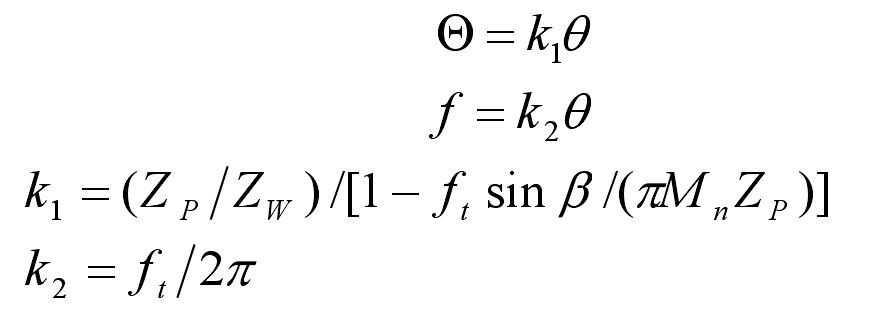
Where:
Θ —— The rotation angle of the tool around the axis of the workpiece;
θ —— Rotation angle of hob;
F — axial displacement of hob;
FT — axial feed speed of hob;
Mn – module of gear;
ZW — number of teeth of gear;
β —— Helix angle of indexing circle of gear;
ZP – number of hob heads.
The tooth groove to be cut is divided into many pieces and layers, that is, the tooth width direction is divided into m equal parts, which is composed of M layers. The top of the tooth groove is angled in the end face along the spiral line of the tooth groove ϕ Divided into N equal parts, the end tooth groove is divided into several small sectors. Through coordinate transformation, the cutting process of hob can be regarded as the cutting process of cutting edge on these sections, so as to calculate the cutting thickness, width, length, cutting area and area moment. At the same time, it can also draw the cutting graphics of each cutter tooth and carry out a series of analysis according to these.