
The structure diagram of an aeroengine is shown in Figure 1.
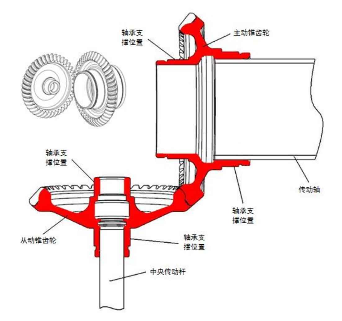
As can be seen from Figure 1, the central driving bevel gear and the driven bevel gear are simply supported, in which the upper end of the driven bevel gear is supported by a stick bearing, the lower end is supported by a ball bearing, the left end of the driving bevel gear is supported by a stick bearing, and the right end is supported by a stick bearing. The driving bevel gear is connected with the high-pressure rotor through a small section of transmission shaft to transmit power. The driven bevel gear is connected with the accessory gearbox through the central transmission rod to transmit power.
Due to the complex structure of aeroengine central bevel gear, it is impossible to obtain accurate results by conventional methods. Therefore, the finite element software ANSYS is used to calculate the natural frequency of aeroengine. In modal analysis, the calculation results are very sensitive to the constrained boundary conditions. For rotating parts, the boundary conditions are difficult to determine. The general treatment method for calculating the natural frequency is to fix them. Considering that there are bearings at both ends of the bevel gear, the constraint is carried out at the node of the corresponding bearing installation position in the finite element mesh. Only radial degrees of freedom are restricted for the radial bearing that can only bear radial force, and radial and axial degrees of freedom are restricted for the radial thrust bearing that can bear both axial force and radial force.
Taking the driven bevel gear as an example, the constraint boundary used in the calculation of natural frequency is explained.
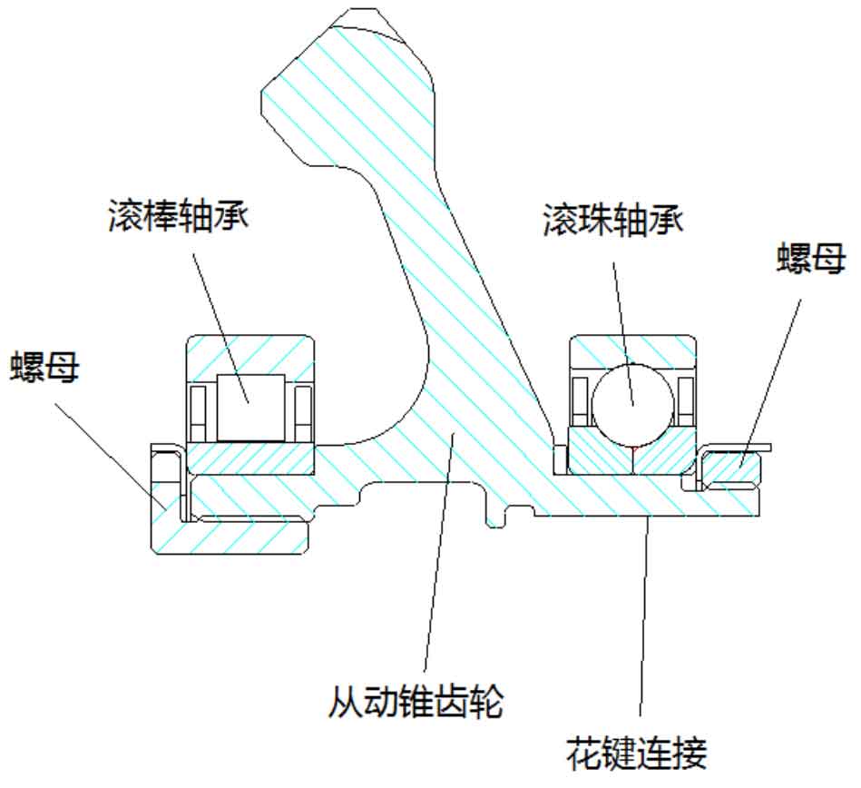
As shown in Figure 2, the driven central bevel gear of an aeroengine is supported on two bearings, one is a ball bearing with thrust function, and the other is a roller bearing that can only bear radial load. The driving bevel gear is connected with the transmission shaft through spline connection, and then connected with the high-pressure shaft of the engine. The driven bevel gear has its own independent support system, and the driving bevel gear is supported in the same way.
The contact surface between ball bearing and bevel gear is defined as a surface and B surface respectively, the spline connection surface of bevel gear is defined as C surface, and the contact surface between roller bearing and bevel gear is defined as D surface. The distribution of each surface on the bevel gear is shown in Figure 3:
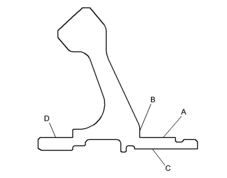
According to the support mode of aeroengine bevel gear, surface a is the installation position of ball bearing, which supports the bevel gear and bears a certain axial force at the same time. Therefore, in the natural frequency calculation, the radial degree of freedom of the node on plane a and the axial degree of freedom of plane B are constrained. The C-plane is the connecting surface between the driving bevel gear and the transmission shaft. The spline connection is adopted to limit the circumferential displacement of the bevel gear, so the circumferential freedom of the node on the C-plane is constrained. Surface D is the installation position of the roller bearing. Because the roller bearing does not bear axial force, it only restricts the radial freedom of surface D. The driven bevel gear is treated according to the same boundary conditions.
In UG model, the smaller structure of bevel gear structure is simplified, such as guide circle and chamfer of non key parts. At the same time, the connecting spline can also be removed. In this way, a high-quality mesh and a relatively small number of meshes are obtained in the finite element mesh generation, which improves the calculation efficiency and saves the calculation time.