
In the realm of high-power marine propulsion, the demand for compact, reliable, and high-torque-density transmission systems is ever-increasing. Traditional single-path gear trains often reach their physical limits in terms of size and load capacity for the most demanding applications. This has led to the widespread adoption of multi-branch, split-torque transmission configurations. Among these, systems utilizing herringbone gear arrangements are particularly favored due to their inherent ability to cancel out axial forces, leading to smoother operation and reduced bearing loads. A prominent design is the coaxial multi-branch system, where power is divided across several parallel paths before being recombined, significantly increasing the total power transmissible within a constrained radial envelope.
The core principle involves an input herringbone gear distributing torque to multiple idler gears, which then drive secondary stages. A critical component in ensuring the longevity and efficiency of such systems is the achievement of equal load sharing among all parallel branches. Uneven loading leads to premature wear, excessive noise, and potential failure of the most heavily loaded path. A common and effective solution to promote load equalization is the introduction of flexibility into the system, typically through the use of compliant, or “elastic,” shafts connecting various stages. While this elasticity successfully improves load distribution, it introduces a significant dynamic consideration: a reduction in the overall stiffness of the transmission system, which consequently lowers its fundamental natural frequencies.
This downward shift in natural frequencies brings them closer to the excitation frequencies generated during operation, such as gear mesh frequencies and their harmonics. The risk of resonance—where an excitation frequency coincides with a system natural frequency—becomes markedly higher. Resonance can precipitate catastrophic vibration amplitudes, dramatically increasing dynamic loads, generating unacceptable noise levels, and accelerating fatigue in gears, shafts, and bearings. Therefore, a thorough understanding of the modal characteristics and resonance behavior is not merely an academic exercise but a fundamental prerequisite for the reliable design of any high-power, multi-branch herringbone gear drivetrain.
This analysis focuses on the dynamics of a representative marine six-branch coaxial herringbone gear transmission system. The primary objectives are to establish its free-vibration characteristics (natural frequencies and mode shapes), identify potential resonance conditions at operational speeds, and investigate the influence of key design parameters—specifically the stiffness of the load-equalizing elastic shafts—on shifting these critical frequencies. The goal is to derive practical guidelines for parameter selection to avoid resonant conditions, thereby informing the vibration reduction design process for these complex systems.
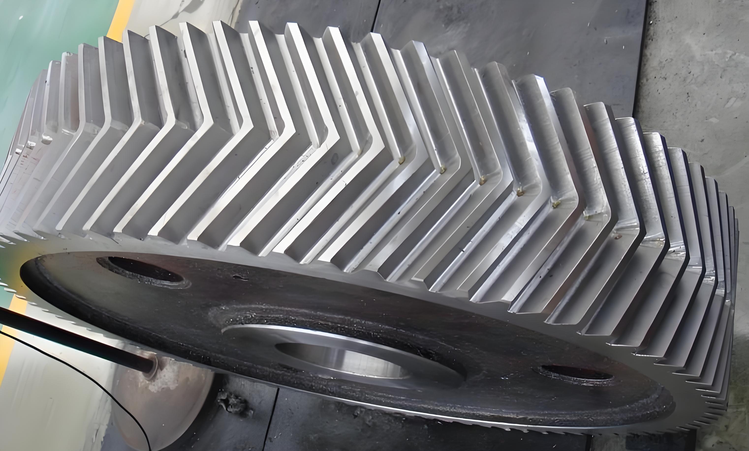
The advantages of the herringbone gear in such applications are manifold. Its double-helical design inherently balances axial thrust, eliminating the need for complex thrust bearings and allowing for more compact bearing arrangements. This leads to a stiffer, more symmetric support for the gear, which is beneficial for dynamic performance. The smooth engagement characteristics also contribute to lower vibration and noise excitation at the source compared to single helical or spur gears.
Methodology: Finite Element Modeling and Modal Analysis
The dynamic analysis of such a geometrically complex system necessitates the use of numerical methods. A three-dimensional finite element model (FEM) was developed using commercial ANSYS software to accurately capture the inertia and stiffness distribution of the entire transmission assembly. The model encompassed all major components: the input pinion, idler gears, output gear, parallel path gears, and the interconnecting shafts, including the crucial elastic shafts designed for load sharing.
To simulate realistic boundary conditions, the model constrained all translational degrees of freedom at the locations corresponding to bearing supports, while retaining the rotational degrees of freedom. This approximates the effect of radial bearings that prevent lateral movement but allow free rotation. The connections between gears and their respective shafts were modeled as bonded contacts, simulating shrink fits or keyed connections. The most critical interactions—the meshing between gear teeth—were modeled as surface-to-surface “no separation” contacts. While this linear contact formulation simplifies the nonlinear stiffness of a gear mesh, it is a standard and effective approach for conducting a modal analysis, which aims to find the inherent system properties independent of the operational force magnitude.
The material properties assigned to all steel components were consistent with high-strength gear alloys:
| Material Property | Value | Unit |
|---|---|---|
| Density (ρ) | 7800 | kg/m³ |
| Young’s Modulus (E) | 207 | GPa |
| Poisson’s Ratio (μ) | 0.25 | – |
The system parameters for the six-branch herringbone gear train are detailed below. The power flow initiates at Gear 1 (input), splits into three paths via idlers (Gears 2), drives the first-stage driven gears (Gears 3), is transferred via elastic shafts to the second-stage pinions (Gears 4), splits again via idlers (Gears 5), and finally recombines at the coaxial output gear (Gear 6).
| Gear Name | Notation | Number of Teeth (z) | Normal Module (mm) | Face Width (mm) | Helix Angle (°) |
|---|---|---|---|---|---|
| Input Pinion | Gear 1 (z1) | 43 | 6 | 202 | 28 |
| 1st Stage Idler | Gear 2 (z2) | 58 | 6 | 202 | 28 |
| 1st Stage Driven | Gear 3 (z3) | 184 | 6 | 202 | 28 |
| 2nd Stage Pinion | Gear 4 (z4) | 37 | 8 | 300 | 28 |
| 2nd Stage Idler | Gear 5 (z5) | 70 | 8 | 300 | 28 |
| Output Gear | Gear 6 (z6) | 173 | 8 | 300 | 28 |
Based on an input speed of 3650 rpm, the rotational and meshing frequencies for each stage are calculated as follows, where `n` is speed in rpm, `f_rot` is rotational frequency in Hz, and `f_mesh` is meshing frequency in Hz:
$$ f_{rot} = \frac{n}{60} $$
$$ f_{mesh} = f_{rot} \times z $$
| Component | Speed (rpm) | Rotational Frequency (Hz) | Meshing Frequency (Hz) |
|---|---|---|---|
| Gear 1 (Input) | 3650 | 60.83 | 2615.8 |
| Gear 2 | ~2706 | ~45.10 | 2615.8 |
| Gear 3 / Gear 4 | ~853 | ~14.22 | 2615.8 / 526.0 |
| Gear 5 | ~451 | ~7.51 | 526.0 |
| Gear 6 (Output) | ~182 | ~3.04 | 526.0 |
The modal analysis solves the classical eigenvalue problem derived from the undamped equations of motion:
$$ [\mathbf{K}] \{\phi\} = \omega^2 [\mathbf{M}] \{\phi\} $$
where \([\mathbf{K}]\) is the global stiffness matrix, \([\mathbf{M}]\) is the global mass matrix, \(\omega\) is the natural angular frequency (rad/s), and \(\{\phi\}\) is the corresponding mode shape vector. The first 20 natural frequencies (\(f = \omega / 2\pi\)) and their associated mode shapes were extracted for the baseline configuration.
Inherent Dynamic Characteristics: Natural Frequencies and Mode Shapes
The results of the modal analysis for the baseline six-branch herringbone gear system are summarized in the table below. The first natural frequency is found at approximately 73.9 Hz, with subsequent modes showing a generally increasing trend.
| Mode Order | Natural Frequency (Hz) | Primary Characteristic |
|---|---|---|
| 1 | 73.94 | Global rotation (Y-axis), 1st stage region |
| 2 | 176.23 | Global rotation (Y-axis), 2nd stage region |
| 3 | 264.11 | Global translation (X-axis) |
| 4 | 272.90 | Global translation (Z-axis) |
| 5 | 326.74 | Rocking/Tilting of 1st stage gears (X-axis) |
| 6 | 339.26 | Rocking/Tilting of 1st stage gears (Z-axis) |
| 7 | 391.53 | Combined bending of shafts |
| 8 | 454.82 | Localized vibration of idler clusters |
| 9 | 476.89 | Localized vibration of idler clusters |
| 10 | 480.41 | Localized vibration of idler clusters |
| 11 | 505.71 | Torsional-bending coupling |
| 12 | 520.59 | Higher-order shaft bending |
| 13 | 552.51 | Complex deformation of multiple paths |
| 14 | 564.79 | Complex deformation of multiple paths |
| 15 | 578.96 | Complex deformation of multiple paths |
| 16 | 586.09 | Complex deformation of multiple paths |
| 17 | 586.73 | Complex deformation of multiple paths |
| 18 | 685.92 | Local gear body modes |
| 19 | 706.29 | Local gear body modes |
| 20 | 755.71 | Local gear body modes |
A key observation is the clustering of natural frequencies at several points (e.g., Modes 3-5, 8-10, 12-14, 15-17). This is a direct consequence of the system’s high degree of symmetry, particularly the existence of three and six identical parallel branches. Symmetric structures often lead to repeated or closely spaced eigenvalues, as the system can vibrate in similar patterns but oriented along different symmetric axes or localized to different, identical substructures.
The first two mode shapes are of particular interest as they represent the lowest energy, and therefore most easily excited, global motions. Mode 1 is characterized by a rigid-body-like rotational oscillation of the entire first-stage gear cluster (input pinion and its three idlers) around the system’s Y-axis (typically the output axis). Mode 2 exhibits a similar rotational oscillation but is primarily localized to the second-stage gear cluster. These modes are predominantly influenced by the torsional and bending compliance of the shafts connecting these subsystems, especially the elastic shafts.
Resonance Risk Assessment via Campbell Diagram
Modal analysis provides the natural frequencies for a non-rotating system. However, when the system operates at high speed, gyroscopic effects and bearing stiffness variations can cause these natural frequencies to shift—a phenomenon known as spin softening or speed-dependent stiffening. To assess the resonance risk at the operational speed, a Campbell diagram is constructed. This plot displays the system’s natural frequencies as a function of rotational speed (often the input shaft speed), along with lines representing potential excitation frequencies.
The most common excitation sources in a herringbone gear transmission are the gear mesh frequencies and their harmonics, as well as shaft rotational frequencies (1x, 2x, etc.) due to residual unbalance. Resonance is predicted to occur when an excitation frequency line intersects a natural frequency line at the operating speed.
For this analysis, the input shaft rotational frequency \(f_{in}\) is 60.83 Hz at the cruise speed of 3650 rpm. Excitations at 1x and 2x this frequency (60.83 Hz and 121.66 Hz) are considered significant. The Campbell diagram analysis revealed a critical finding:
- No intersection occurred between the 1x excitation line and the first 20 natural frequency curves within the operating speed range.
- However, the 2x excitation line (representing 2nd order unbalance or certain nonlinear effects) intersected the first natural frequency curve at a speed very close to the nominal operating speed.
The intersection point was identified at approximately 3133 rpm, with a corresponding frequency of 104.4 Hz. Given that the operational cruise speed is 3650 rpm, and considering a typical engineering safety margin of 10-15% for critical speeds, the calculated critical speed (3133 rpm) falls within the range of 3102.5 rpm to 4197.5 rpm. This indicates a high risk of resonance near the cruise condition. The excitation at twice input shaft frequency could excite the first global rotational mode of the first-stage herringbone gear cluster, leading to amplified vibrations.
Parametric Study: Influence of Elastic Shaft Stiffness
The elastic shaft, primarily intended for load equalization, is a key design parameter that directly controls the system’s global stiffness. Its stiffness \(k_{shaft}\) is a function of its geometry (diameter `d`, length `L`) and material modulus `G` for torsion, and `E` for bending:
Torsional Stiffness: $$ k_t = \frac{G J}{L}, \quad J = \frac{\pi d^4}{32} $$
Bending Stiffness: $$ k_b \propto \frac{E I}{L^3}, \quad I = \frac{\pi d^4}{64} $$
Clearly, the shaft diameter `d` is the most dominant factor, as stiffness is proportional to the fourth power of the diameter. The support span (length `L`) also plays a major role, especially for bending stiffness, which is inversely proportional to the cube of the length.
To guide design away from resonance, a parametric study was conducted to quantify the effect of changing the elastic shaft’s diameter and support span on the system’s first natural frequency.
Effect of Shaft Diameter
The baseline shaft diameter was 240 mm. The diameter was varied while keeping all other parameters, including the span, constant. The first natural frequency was calculated for each configuration.
| Shaft Diameter (mm) | 1st Natural Frequency (Hz) | Critical Speed for 2x Excitation (rpm) |
|---|---|---|
| 200 | 102.16 | 3064.9 |
| 220 | 103.76 | 3112.9 |
| 240 (Baseline) | 104.44 | 3133.2 |
| 260 | 105.63 | 3169.0 |
| 280 | 108.35 | 3250.6 |
The results show a clear trend: increasing the shaft diameter increases the first natural frequency. This is because the increase in bending and torsional stiffness (proportional to `d^4`) outweighs the associated increase in mass (proportional to `d^2`). Consequently, the critical speed where the 2x line intersects this frequency also increases. For the 200 mm diameter shaft, the critical speed (3065 rpm) moves to the lower boundary of the 10-15% margin range around 3650 rpm, potentially moving it out of the “danger zone.” This suggests that a reduction in shaft diameter from the baseline could be a viable strategy to avoid the identified resonance, provided the reduced stiffness still meets the load-sharing requirements and strength criteria.
Effect of Support Span (Shaft Length)
Next, the distance between the supports for the elastic shaft (the span) was varied, while the diameter was held at the baseline 240 mm. Increasing the span effectively increases the unsupported length of the shaft, reducing its effective bending stiffness.
| Support Span (mm) | 1st Natural Frequency (Hz) | Critical Speed for 2x Excitation (rpm) |
|---|---|---|
| 610 (Baseline) | 104.44 | 3133.2 |
| 650 | 103.98 | 3120.5 |
| 690 | 103.53 | 3105.9 |
| 730 | 102.86 | 3093.7 |
The opposite trend is observed here: increasing the support span decreases the first natural frequency. This is due to the significant reduction in bending stiffness, which is inversely proportional to the cube of the length (`L^3`). The associated increase in shaft mass is linear with length, so the stiffness reduction dominates. The critical speed correspondingly decreases. Therefore, to raise the critical speed away from the operating point, one should minimize the support span where possible, making the shaft stiffer in bending.
Discussion and Integrated Design Strategy
The analysis conclusively demonstrates that the design of the elastic shaft in a multi-branch herringbone gear system is a critical exercise in dynamic tuning, not just static load sharing. The stiffness of this component is the primary lever for adjusting the system’s fundamental natural frequency. The parametric study provides a clear directional guide:
- To increase the natural frequency and raise the critical speed, the designer should:
- Increase the shaft diameter (most effective).
- Decrease the support span (shorter shaft).
- To decrease the natural frequency and lower the critical speed, the opposite adjustments should be made.
For the specific case study with a cruise speed of 3650 rpm and a 2x excitation risk, the baseline design (240 mm dia.) places the critical speed (3133 rpm) within the resonant margin. The data indicates that reducing the shaft diameter to 200 mm or increasing it to 280 mm both shift the critical speed, but in opposite directions. A reduction to 200 mm lowers the critical speed to 3065 rpm, potentially moving it below the 10% safety margin (which starts at 3102.5 rpm for 3650 rpm). This might be the preferable corrective action, as it also maintains a higher degree of flexibility for load equalization. However, a thorough stress analysis under maximum torque is required to ensure the smaller shaft is adequate.
Alternatively, decreasing the support span offers another route to increase stiffness and natural frequency without changing the diameter. An integrated approach would involve multi-objective optimization, where the elastic shaft’s dimensions are variables, and the constraints include:
1. Minimum stiffness for acceptable load-sharing coefficients.
2. Maximum stress under peak torque.
3. A forbidden frequency range (e.g., ±15% around 2x input frequency at cruise).
4. Physical packaging constraints (maximum diameter, minimum span).
The dynamic model can be extended to perform a forced response analysis, calculating vibration amplitudes under actual gear meshing forces. This would allow for a more precise evaluation of the severity of a near-resonance condition and the effectiveness of the proposed stiffness changes. Furthermore, incorporating nonlinear bearing stiffness and damping models would enhance the prediction accuracy, especially for modes involving significant support motion.
Conclusion
The dynamic integrity of a high-power, six-branch coaxial herringbone gear transmission system is fundamentally governed by its modal properties and the risk of resonant excitation. This analysis has established a clear methodology and yielded critical insights:
- The finite element modal analysis successfully identified the natural frequencies and mode shapes of the complex system, revealing a first global mode susceptible to excitation at twice the input shaft frequency.
- The Campbell diagram is an essential tool for resonance identification, pinpointing a critical speed near the operational cruise condition for the baseline design.
- The stiffness of the load-sharing elastic shaft is the paramount parameter influencing the system’s fundamental natural frequency. Its design cannot be based on static criteria alone.
- A direct relationship exists: shaft natural frequency increases with diameter (≈ `d^2` relationship dominant in effect) and decreases with support span length (≈ `1/L^3` relationship).
- To avoid the identified resonance, the elastic shaft stiffness must be deliberately tuned. For the case studied, reducing the shaft diameter from the baseline value or shortening its support span are viable strategies to shift the critical speed outside the dangerous margin around the operating speed.
In summary, the design of multi-branch herringbone gear systems must adopt a holistic, dynamics-first approach. The elastic elements introduced for mechanical performance (load sharing) must be co-designed with the dynamic performance (resonance avoidance) as a primary objective. The parametric guidelines established here provide a foundational framework for engineers to navigate this trade-off, leading to the development of more robust, quiet, and reliable marine propulsion transmission systems. Future work should integrate system-level forced response and nonlinear effects to further refine these design principles.