
Fatigue failure is a pervasive and critical phenomenon in engineering structures and mechanical equipment. Statistics indicate that between 50% to 90% of mechanical component failures are attributed to fatigue. Among these critical components, bevel gears, serving as essential power transmission elements in drivetrains, are particularly susceptible to fatigue-related failures. The failure of a bevel gear can lead to catastrophic wear of the entire transmission system and, in the context of an aircraft engine, result in a complete loss of propulsion. Therefore, investigating the root causes of bevel gear fatigue is of paramount engineering significance. While many studies on gear fatigue focus on material properties, heat treatment, and metallurgical defects, the influence of geometric and manufacturing factors—such as root fillet dimensions and surface finish—is often overlooked. This case study presents a comprehensive investigation into the bending fatigue failure of an upper drive active bevel gear from a helicopter engine, integrating macro- and micro-fractography, metallurgical examination, dimensional inspection, and advanced finite element analysis (FEA) to pinpoint the failure mechanism.
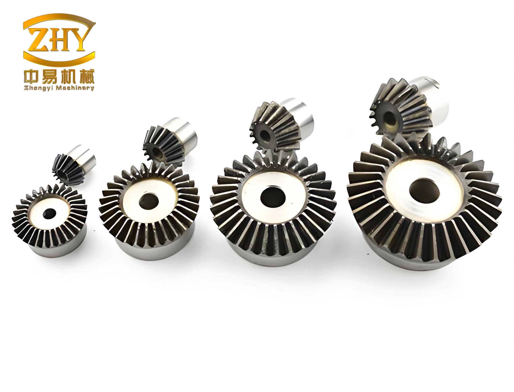
The subject component was an 18Cr2Ni4WA steel bevel gear with an integrated shaft design. The gear teeth were carburized to a specified case depth, with a surface hardness requirement of ≥58 HRC and a core hardness range of 35-45 HRC. The failed gear was removed from service after approximately 362 hours of operation during a routine engine inspection, where a single tooth was found to be fractured. In the engine’s operational cycle, this bevel gear meshes with a driven bevel gear on two distinct flanks: the “starting flank” during engine start and the “working flank” during normal engine operation.
The investigation commenced with a detailed visual and fractographic examination. The fractured tooth exhibited a characteristic “spoon-shaped” or “dug-out” profile at the root on both flanks, indicative of bending-induced failure. Close inspection of the contact patterns on the tooth flanks revealed a significant and consistent deviation. The contact marks on all teeth, including the fractured one and its neighbors, were located abnormally close to the tooth tip (radially) and biased towards the smaller-diameter end of the bevel gear (axially). This abnormal contact pattern was the first clue suggesting a misalignment or incorrect meshing position.
Macroscopic examination of the fracture surface revealed two distinct regions. Approximately 80% of the surface was relatively flat, marked by visible progression lines or “beach marks” radiating from a specific origin. The remaining area was rougher and more irregular. The convergence of the progression lines clearly identified the fatigue origin to be at the root fillet surface on the working flank, very close to the small-diameter end of the gear. Scanning Electron Microscopy (SEM) confirmed the fatigue mechanism. The origin region was a linear source approximately 2 mm in length, free of any inherent material defects like inclusions or voids. The crack propagation area exhibited clear fatigue striations, the microscopic hallmark of cyclic crack advancement. The final rupture zone showed features of ductile overload.
A critical part of the analysis involved meticulous dimensional inspection of the failed bevel gear, with comparisons made against drawing specifications and a reference gear that had successfully accumulated 1000 service hours. The results were revealing.
| Inspection Parameter | Drawing Specification | Failed Gear | Reference Gear (1000 Hrs) |
|---|---|---|---|
| Tooth Thickness (mm) | 3.100 -0.060 | 3.30 | 3.108 |
| Tooth Root Fillet Radius, Small End (mm) | 0.3 – 0.4 | 0.44 – 0.58 (Variable) | Conforms to Spec |
| Tooth Root Fillet Radius, Large End (mm) | 0.3 – 0.4 | 0.67 – 0.72 | Conforms to Spec |
The tooth thickness of the failed gear was measured at 3.30 mm, significantly exceeding the maximum allowable limit of 3.10 mm—an over-thickness of 0.20 mm. Furthermore, the root fillet radii at the small end, while within the specified range on paper, showed variability and, more importantly, poor transitional blending. Examination under a microscope revealed distinct “tool lead-out marks” or sharp edges at the blend between the machined root fillet and the tooth flank. In contrast, the large-end fillets were consistently larger and smoother. The material quality was verified through metallurgical analysis. The carburized case depth, surface microhardness, and core hardness all met the specified requirements, and the microstructure was deemed normal with no evidence of degradation.
The integration of all observational and metrological data led to the definitive conclusion that the failure mode was bending fatigue originating at the root fillet on the working flank. The absence of material defects and the conformity of heat treatment indicated that the root cause was not a deficiency in the gear’s fatigue resistance but rather an excessive applied bending stress. Two primary, interconnected factors were identified: geometric error-induced misalignment and stress concentration due to poor manufacturing.
1. The Effect of Tooth Thickness Error and Resultant Misalignment: The 0.20 mm over-thickness of the failed bevel gear had a direct and severe consequence. During assembly, to achieve the specified gear mesh backlash, the excessive tooth thickness forced the mating gears to be installed with an axial offset from their theoretical design positions. This assembly error, though compensating for backlash, drastically altered the contact pattern. Instead of the ideal contact across the center of the tooth flank, the load was concentrated near the tip and the small-diameter end. This shift in the load application point significantly increases the bending moment arm at the tooth root. The fundamental bending stress at the root of a gear tooth can be approximated by the Lewis formula:
$$
\sigma_b = \frac{F_t}{b m_n Y}
$$
where $\sigma_b$ is the bending stress, $F_t$ is the tangential load, $b$ is the face width, $m_n$ is the normal module, and $Y$ is the Lewis form factor. When the load $F_t$ is applied near the tip, the effective lever arm increases, leading to a substantial rise in $\sigma_b$. The abnormal contact pattern observed on the failed gear was the physical manifestation of this phenomenon.
2. The Effect of Root Fillet Stress Concentration: The variable and poorly finished root fillet at the small end, particularly the presence of sharp tool lead-out marks, acted as a potent stress concentrator. The theoretical stress concentration factor $K_t$ for a notch is highly sensitive to the notch root radius $\rho$. A sharp edge has a very small effective $\rho$, leading to a high $K_t$. The actual bending stress is amplified:
$$
\sigma_{max} = K_t \cdot \sigma_{nominal}
$$
The combination of an already elevated nominal bending stress (from misalignment) and a high stress concentration factor created a local maximum stress at the small-end root fillet that exceeded the material’s endurance limit, initiating a fatigue crack.
To quantitatively assess the individual and combined impact of these factors, a two-pronged Finite Element Analysis (FEA) approach was employed.
FEA 1: Modeling the Tool Lead-Out (Sharp Edge) Effect. A 2D plane-strain model of a gear tooth section was created. Analyses were run with a perfect fillet and with simulated sharp edges of varying heights at the root. The results unequivocally demonstrated the detrimental impact.
| Nominal Fillet Radius (mm) | Sharp Edge Height (mm) | Max. Root Bending Stress (MPa) | Stress Increase vs. Perfect Fillet |
|---|---|---|---|
| 0.3 | 0 (Perfect) | 300 | Baseline |
| 0.12 | 375 | +25% | |
| 0.18 | 385 | +28% | |
| 0.4 | 0 (Perfect) | 265 | Baseline |
| 0.16 | 365 | +38% | |
| 0.24 | 375 | +42% |
The analysis confirmed that even a small sharp edge could increase the local bending stress by 25-40%, severely compromising the gear’s fatigue life. This validated the hypothesis that the observed machining imperfection was a major contributing factor.
FEA 2: Modeling the Assembly Error Due to Tooth Thickness Error. A full 3D nonlinear contact model of the mating bevel gear pair was developed. The model simulated the nominal meshing condition and two error scenarios: one where the driving (active) gear was axially offset by +0.2 mm, and another where the driven gear was offset by the same amount, both representing potential assembly corrections for the thick tooth.
| Assembly Condition | Contact Pattern Location | Approx. Increase in Max. Root Bending Stress | Remarks |
|---|---|---|---|
| Nominal (Theoretical) | Centered on flank | Baseline | Ideal condition |
| Active Gear offset +0.2mm | Biased towards root of active gear | ~ +50% | Explains high stress at root |
| Driven Gear offset +0.2mm | Biased towards tip of active gear | ~ +60% | Explains observed tip contact & high stress |
The 3D FEA provided critical insights. The scenario where the driven gear was offset (simulating compensation for the thick active gear) produced a contact pattern biased towards the tip of the active gear’s teeth—exactly as observed on the failed component. This condition also predicted a dramatic ~60% increase in the maximum root bending stress. When this amplified stress was combined with the stress concentration factor from the poor fillet finish (an additional 30-40% increase), the resultant stress easily surpassed the fatigue strength of the material, leading to the initiation and propagation of a fatigue crack from the most vulnerable point: the poorly finished root fillet at the small-diameter end.
In conclusion, the fracture of the helicopter transmission bevel gear was a direct result of a bending fatigue mechanism. The root cause was not a material deficiency but an operational stress state that far exceeded design expectations. This overstress condition was the synergistic product of two manufacturing-related issues:
- Geometric Error (Tooth Thickness): The excessive tooth thickness forced an assembly misalignment, shifting the load path to the most mechanically disadvantaged location on the tooth (near the tip), which massively increased the nominal bending moment at the root.
- Manufacturing Defect (Root Fillet Quality): The poorly machined root fillet with sharp transitional edges at the critically stressed small-diameter end introduced a severe stress concentration, locally amplifying the already elevated bending stresses.
The finite element analysis effectively quantified the contribution of each factor, demonstrating how their combination led to catastrophic failure. This failure analysis underscores a critical lesson for the design and manufacturing of high-integrity bevel gears: stringent control over both macro-geometry (tooth dimensions) and micro-geometry (surface finish, fillet blends) is non-negotiable. Tolerances are not merely numbers on a drawing; they are integral to the functional stress state of the component. Following this investigation, corrective actions were implemented, focusing on enhancing process controls for tooth grinding to guarantee thickness conformity and instituting rigorous visual and tactile inspection standards for root fillet quality, particularly at the high-stress small-diameter end of the tooth. These measures have proven effective in preventing the recurrence of such failures, ensuring the reliable performance of these critical transmission bevel gears.