
Precision forging of spur gears represents a pivotal manufacturing technique, offering significant advantages in material savings, production efficiency, and enhanced mechanical properties of the final component. The process aims to produce near-net-shape spur gear teeth directly from a metal billet, minimizing or eliminating subsequent machining. However, the very nature of forming the complex tooth profile, particularly filling the sharp corners of the die cavity, presents a formidable challenge. This challenge manifests as exceptionally high forging loads during the final stages of deformation.
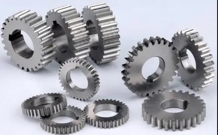
These high loads are detrimental for several reasons. They demand larger, more expensive forging presses, increase energy consumption, and, most critically, impose extreme stresses on the forging die. The high cavity pressure, especially concentrated at the tooth corners, drastically shortens die life due to accelerated wear, plastic deformation, or catastrophic cracking. Furthermore, excessive elastic deformation of the die under high pressure can compromise the dimensional accuracy of the forged spur gear. Therefore, the central problem in spur gear precision forging is to ensure complete cavity filling while simultaneously mitigating the peak forging load to enhance process viability, die longevity, and product precision.
This article delves into the core issue of load reduction in closed-die forging of spur gears. Based on an analysis of the factors influencing forming load, a novel process strategy is proposed and investigated. The core idea revolves around the principle of “pressure relief” or “flow division.” While ensuring the complete filling of the tooth profile, a controlled pathway is created to allow some material to flow into a designated “relief” area. This action alters the internal stress state from a fully constrained triaxial compression, thereby reducing the resistance to metal flow into the final, difficult-to-fill regions. The proposed methodology involves a two-stage process: preforging to create a preliminary spur gear shape with a deliberately designed internal relief hole, followed by a final forging stage where this hole acts as an active flow divider. The effects of this process on metal flow behavior and the resultant forging load are systematically analyzed through finite element simulation and experimental validation, demonstrating its efficacy in producing a fully formed spur gear under significantly lower loads.
Theoretical Foundation for Load Reduction in Spur Gear Forging
The closed-die forging of a spur gear can be conceptually simplified as an axisymmetric upsetting process with radial flow constrained by a complex peripheral cavity—the tooth spaces. In the final stages, as the tooth corners remain unfilled, the workpiece material is subjected to a severe state of triaxial compressive stress. The yielding of the material under such conditions is governed by the von Mises yield criterion. For a three-dimensional stress state with principal stresses \(\sigma_1\), \(\sigma_2\), and \(\sigma_3\), the criterion states that yielding begins when the distortional energy reaches a critical value:
$$
\sigma_Y = \frac{1}{\sqrt{2}} \sqrt{(\sigma_1 – \sigma_2)^2 + (\sigma_2 – \sigma_3)^2 + (\sigma_3 – \sigma_1)^2}
$$
Where \(\sigma_Y\) is the yield stress of the material. In the confined corners of the spur gear die, achieving the necessary stress differential to satisfy this yield condition becomes increasingly difficult. The material’s flow stress also increases due to work hardening. Consequently, enormous pressure must be applied to force the material to yield and flow into these corners.
The total forging load \(F\) required for plastic deformation can be expressed by a general formula:
$$
F = K \cdot \sigma_s \cdot A
$$
Where:
\(\sigma_s\) is the flow stress of the material (which increases with strain and strain rate),
\(A\) is the projected contact area between the workpiece and the die in the direction of the forging force,
\(K\) is the constraint factor (or stress state factor).
This factor \(K\) is crucial. For unconstrained deformation (e.g., free upsetting), \(K \approx 1\). For deformation under increasing constraint, such as in closed-die forging, \(K\) becomes greater than 1, often significantly so in the final filling stages. This factor encapsulates the additional energy required to overcome frictional forces and, more importantly, the geometrical constraint that forces the material into a complex shape. For a spur gear being forged in a closed die, the value of \(K\) escalates dramatically as the tooth corners are being filled, leading to the sharp rise in load observed in conventional processes.
The proposed solution of “flow division” directly targets this constraint factor \(K\). By intentionally creating an additional, easier flow path (the relief hole) during the final forging stage, the severe geometrical constraint is alleviated. The material now has two directions to flow: into the tooth corners and into the relief hole. This effectively reduces the apparent constraint factor for the corner-filling operation, as predicted by the equation. While the contact area \(A\) may slightly increase, the reduction in \(K\) dominates, leading to a net decrease in the total forging load \(F\). This principle forms the theoretical backbone of the two-stage spur gear forging process developed in this work.
Process Design and Methodology: Preforging with a Relief Hole
The novel process for precision forging of spur gears consists of two distinct but sequential stages performed in a single die set with a tooling change for the upper punch. The design philosophy is rooted in near-net-shape principles: the functionally critical tooth profile is forged to its final dimensions, while excess material is strategically directed to a sacrificial region that is later removed with minimal machining.
Stage 1: Preforging for Preliminary Shape and Relief Hole Formation
The first stage employs a multi-action die. The initial cylindrical billet is placed into a floating die cavity containing the negative tooth profile of the spur gear. The upper punch, which features a central, shaped mandrel (e.g., with a spherical or conical tip), descends. As the billet is compressed axially, its height decreases, and it expands radially to fill the tooth spaces. Concurrently, the central mandrel pierces or displaces material to form a preliminary relief hole. The primary objectives of this stage are:
1. To achieve a significant pre-form of the spur gear teeth, reducing the filling required in the final stage.
2. To create a pre-defined internal relief hole. The shape and size of this hole are critical design parameters.
3. To control the metal flow to favor filling of the upper tooth corners first, due to the influence of the mandrel’s shape.
The preforging stage is terminated just as the tooth profile is nearly complete, and the load begins its rapid ascent, indicating the onset of high constraint.
Stage 2: Final Forging with Active Flow Division
For the second stage, the upper punch is swapped for a final forging punch. A key feature of this stage is the retraction of the central mandrel, which enlarges the pre-formed relief hole, creating a cavity. The final punch then continues the downward stroke. Now, the material is subjected to further compression. The crucial difference from conventional forging is the presence of the open relief cavity. The metal now has two competing flow paths: it can continue to flow radially outward to complete the filling of the remaining unfilled tooth corners (typically the lower ones), and it can flow inward into the central relief cavity. This active flow division maintains a lower level of triaxial constraint. Once the tooth corners are completely filled, any additional material displacement is accommodated almost entirely by flow into the relief cavity, forming a small flash. This final stage ensures dimensional accuracy of the spur gear teeth under a controlled and reduced load.
The die assembly is designed to allow for these actions. A floating die arrangement helps in ejecting the forged spur gear part after the process is complete. The process parameters, such as the initial billet dimensions, the size and geometry of the relief hole, and the amount of mandrel retraction, are optimized to balance load reduction with complete tooth fill and minimal flash generation.
The design of the initial billet is based on volume constancy, ensuring the volume of the billet equals the volume of the final spur gear plus the volume of the flash in the relief area. For a spur gear with module \(m=3\), number of teeth \(z=18\), pressure angle \(\alpha=20^\circ\), and thickness \(h=20\) mm, the billet diameter and height are calculated accordingly.
Finite Element Analysis of Metal Flow and Load Characteristics
To analyze the proposed spur gear forging process in detail, a three-dimensional finite element (FE) model was developed. Leveraging the symmetry of the spur gear, a 1/18th sector (a single tooth) was modeled to reduce computational cost. The workpiece material (modeled as AL1100) was defined as a rigid-plastic body, obeying the material’s flow stress law. The dies (upper punch, lower punch, central mandrel, and floating die) were modeled as rigid bodies. A shear friction model with a coefficient of 0.12 was applied at all tool-workpiece interfaces. The simulation was conducted at room temperature with a constant punch velocity of 10 mm/s.
Metal Flow and Deformation Patterns
The simulation revealed distinct metal flow patterns in each stage. During preforging, the material flows radially outward under the axial compression from the punch. The presence of the central mandrel significantly influences this flow. Material in contact with the mandrel’s tip experiences higher resistance to flow, while material away from it flows more freely into the tooth cavity. This results in a non-uniform filling pattern where the upper regions of the tooth profile (near the punch) tend to fill more readily than the lower regions. A preliminary relief hole is successfully formed.
In the final forging stage, with the mandrel retracted, the flow field changes. The material now exhibits a combined flow pattern: it flows both outward to complete the filling of the lower tooth corners and inward to fill the enlarging central relief cavity. This dual-flow mode is the essence of the load-reduction mechanism. The velocity vectors clearly show material moving into the relief hole even as the last corners of the spur gear tooth are being filled. Once the tooth profile is completely filled, the inward flow into the relief cavity becomes predominant, resembling a forward extrusion process, which requires a relatively steady and lower load compared to constrained corner filling.
Influence of Relief Hole Size on Forging Load
A critical study was performed to quantify the impact of the relief hole size on the final forging load. Four different design scenarios were simulated: a conventional process with no relief hole, and the proposed process with pre-formed relief holes of radii \(R = 5\) mm, \(R = 10\) mm, and \(R = 15\) mm. The load-stroke curves for these cases are fundamentally different.
The conventional process shows a load curve that rises steeply from the beginning and then undergoes an extremely sharp increase in the final filling stage, reaching a peak load of approximately 1109 kN. In contrast, the load curves for the processes with a relief hole show two distinct rising segments. The first segment corresponds to the preforging stage, where the load increases as the preliminary spur gear shape is formed. The size of the relief hole has a minimal effect on the final preforging load. The second segment corresponds to the final forging stage. Here, the influence of the relief hole radius is profound.
| Relief Hole Radius (mm) | Final Forging Load (kN) | Load Reduction vs. Conventional Process |
|---|---|---|
| 0 (Conventional) | 1109 | 0% (Baseline) |
| 5 | 852 | 23.2% |
| 10 | 690 | 37.8% |
| 15 | 498 | 55.1% |
The data clearly indicates that a larger relief hole leads to a more gradual load increase during final forging and a significantly lower peak load. This is because a larger hole offers a lower resistance flow path, more effectively relaxing the triaxial stress state in the deforming spur gear. However, there is a trade-off. An excessively large relief hole, while minimizing load, may lead to incomplete filling of the hole itself and generates more flash material that must be trimmed, increasing waste. For the specific spur gear under consideration, a relief hole radius of 5 mm was selected for further experimental study as it provided a substantial load reduction (over 23%) while maintaining good control over material utilization and final part geometry.
Experimental Validation and Results
To validate the FE simulation results and demonstrate the practical feasibility of the process, experimental trials were conducted. Cylindrical billets of AL1100, with dimensions calculated for volume consistency, were used. The billets were lubricated with molybdenum disulfide to reduce friction. The two-stage forging was performed on a 3150 kN hydraulic press using a specially designed die set that accommodated the floating die, the central mandrel mechanism, and interchangeable upper punches for the preforging and final forging stages.
The experimental outcomes successfully mirrored the simulation predictions. After the first stage, a preform was obtained showing a spur gear with partially formed teeth having large corner radii and a clearly formed central relief cavity. Subsequently, the final forging stage was carried out. At a final recorded load of approximately 721 kN, a fully formed spur gear was produced. Visual inspection confirmed that the tooth profiles were completely and sharply filled, requiring no further machining on the teeth. The central relief area contained a formed flash, which is easily removed in a secondary trimming operation. This flash represents the sacrificial material that enabled the load reduction and complete fill.
A comparison between the experimental and simulated load-stroke curves showed excellent agreement. Both curves for the process with the relief hole exhibited the characteristic two-stage rise, with the final load being significantly lower and rising more gradually compared to the simulated curve for the conventional process (without a relief hole), which showed a steep, unchecked load increase at the end. The minor differences between experiment and simulation (e.g., a slightly higher experimental load) can be attributed to factors like slight variations in friction, material properties, and machine stiffness, which are perfectly acceptable in engineering validation.
Discussion and Comparative Advantages
The proposed “preforging with a relief hole – final forging with flow division” process presents a compelling alternative to traditional spur gear precision forging methods. Its advantages stem from the intelligent control of metal flow and stress state.
1. Substantial Load Reduction: As quantitatively demonstrated, the process can reduce the final forging load by 23% to over 55%, depending on the designed relief hole size. This directly translates to the use of smaller-capacity, less expensive forging presses, lower energy consumption, and reduced machine tool wear.
2. Enhanced Die Life: The lower forming load results in significantly lower cavity pressure, especially at the critical tooth corners. This reduction in stress dramatically decreases die wear, minimizes the risk of plastic deformation of the die edges, and virtually eliminates die failure due to cracking caused by excessive tensile stresses. The economic benefit of extended die life is substantial in mass production of components like spur gears.
3. Improved Dimensional Accuracy: Lower die pressures also mean reduced elastic deformation (springback) of the die itself during the forging stroke. This leads to better consistency and accuracy in the dimensions of the forged spur gear, moving closer to true net-shape manufacturing.
4. Guaranteed Fill: The process actively manages flow to ensure complete filling of the tooth profile. The initial preform stage achieves a significant fill, and the final stage uses flow division to coax material into the last corners without requiring excessive force.
5. Process Simplicity and Efficiency: Compared to other proposed load-reduction methods for spur gears—such as those requiring complex multi-action die movements, complete part transfer between different dies, or machining of tooth tips—this process is relatively simple. It requires only a change of the upper punch between stages, maintaining high production efficiency suitable for industrial application.
The key to optimizing this process lies in the careful design of the relief hole geometry (size and shape) and the preform shape. The goal is to find the minimum relief volume that provides the necessary load reduction and filling assurance, thereby maximizing material yield. Advanced process simulation tools, as used in this study, are indispensable for this optimization without the need for costly physical trial-and-error.
Conclusion
The precision forging of spur gears is significantly enhanced by the implementation of a controlled flow division strategy. The two-stage process involving preforging to create a relief hole followed by final forging with an active分流 cavity has been proven effective through combined finite element analysis and experimental validation. The core mechanics involve altering the detrimental triaxial compressive stress state in the final filling phase by providing an engineered escape path for material flow. This action directly reduces the constraint factor (K) in the fundamental forging load equation, leading to a dramatic decrease in the required forging force.
The results consistently show that this methodology enables the production of a spur gear with fully filled, precise tooth profiles under loads that are substantially lower than those required in conventional closed-die forging. The benefits cascade into longer die life, improved part accuracy, and the potential for using smaller equipment. This approach represents a strategic advancement in near-net-shape forging technology, addressing the primary technical and economic barriers associated with the precision forming of complex components like spur gears. Future work may focus on extending this principle to other challenging forged geometries and optimizing the preform and relief design through advanced multi-objective algorithms to further push the boundaries of efficiency and precision in metal forming.