
In my daily work with internal gear production, the most persistent shop-floor problem is not the cutting itself but the choice of the correct gear shaping cutter before the first part reaches the machine. Internal gears for crowned-tooth couplings and similar products often use the major diameter as the locating datum, while the root diameter and the pin distance must remain inside strict tolerance bands. Many drawings are non-standard, and the same module and pressure angle can hide a wide range of modification coefficients, tooth heights, and pin-distance limits. In this environment, a gear shaping cutter that looks acceptable on paper can produce a gear whose pin distance is already above the maximum while the root diameter has not yet reached the minimum. The operator then faces a difficult choice: continue cutting and risk scrap, stop and search for another cutter, or wait for a new non-standard cutter to be ordered. My approach is to replace trial cutting with a deterministic calculation and selection process. The method combines internal gear geometry, pin measurement, cutter working-section geometry, internal meshing equations, and a dynamic gear shaping cutter inventory. The result is a fast, repeatable, and economic way to select the best available gear shaping cutter while avoiding top-cutting interference and reducing unnecessary waiting time.
1. Why Gear Shaping Cutter Selection Must Be Calculated
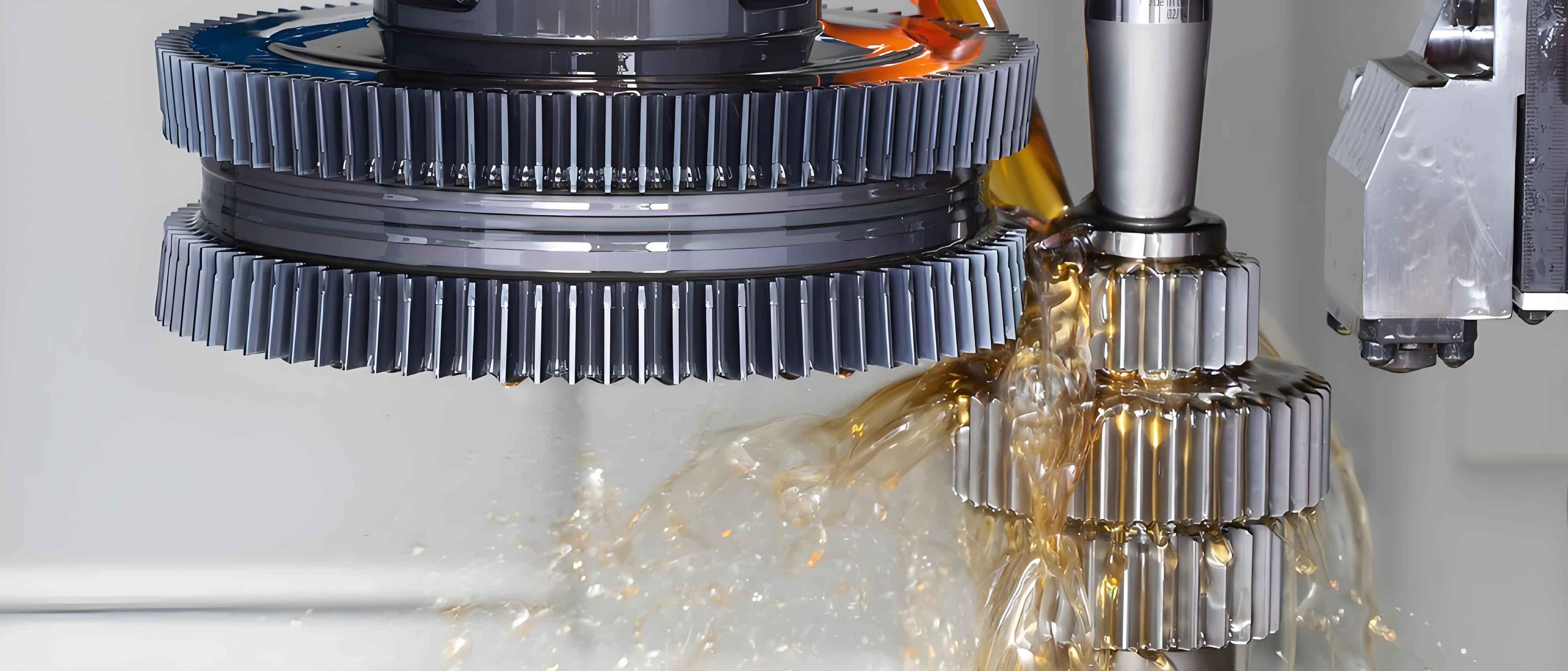
Gear shaping is a generating process. The gear shaping cutter is a gear-like tool whose cutting edges are formed by a rake face and a relief flank. During gear shaping, the cutter reciprocates, rotates in a timed relationship with the workpiece, and gradually generates the involute profile. Because the cutter has relief on both the top and the flanks, every regrinding changes the working section. A gear shaping cutter is therefore not a single fixed gear; it is a family of virtual gears whose modification coefficient changes from the front face toward the original section. This is the central reason why cutter selection for internal gears cannot be based only on module, pressure angle, and tooth count. The same gear shaping cutter can cut gears with different modification coefficients, but it cannot always satisfy a simultaneous root-diameter limit and pin-distance limit. The selection calculation must therefore include the actual working-section data of the cutter.
In my experience, three failure modes dominate. First, the pin distance reaches its upper limit before the root diameter reaches its required value. Second, the root diameter reaches its lower limit too early, leaving no room to finish the pin distance. Third, the cutter tip interferes with the internal gear tip, producing top-cutting or a visible corner cut. All three can be avoided if the internal gear envelope and the gear shaping cutter envelope are calculated before cutting. The purpose of the selection method is not to find a cutter that is merely “close enough” but to find a cutter whose generated root diameter and pin distance both fall inside the drawing tolerance band, or to identify a controlled partial-tooth cutting strategy when no perfect match exists.
2. Internal Gear Parameter Envelope
An internal gear drawing normally gives the module, pressure angle, number of teeth, tip diameter, maximum and minimum root diameter, pin diameter, and maximum and minimum pin distance. Sometimes the nominal modification coefficient, addendum coefficient, and dedendum coefficient are also given, but I never rely on nominal values alone. I treat the drawing as an envelope. The pin distance range can be converted into a modification coefficient range, and the root diameter range can be converted into a root-height range. The ideal target is the middle of both tolerance bands. This is important for gear shaping because non-standard cutters are usually designed around the middle of the tolerance band, and production has the best chance of satisfying both limits when the generated values sit near the center rather than at an edge.
The main symbols I use are summarized below. Angles in the calculation are in radians when they appear in the involute function.
| Symbol | Meaning |
|---|---|
| m | Module |
| α | Pressure angle |
| z2 | Number of teeth of the internal gear |
| z0 | Number of teeth of the gear shaping cutter |
| da2 | Tip diameter of the internal gear |
| da0 | Tip diameter of the gear shaping cutter in the working section |
| df2 | Root diameter of the internal gear generated by gear shaping |
| dp | Diameter of the measuring pin |
| M | Pin distance, also called pin-center distance or ball distance |
| x2 | Modification coefficient of the internal gear |
| x0 | Modification coefficient of the gear shaping cutter working section |
| αM | Pressure angle at the pin center circle |
| α’ | Mesh angle during gear shaping |
| A | Center distance during gear shaping |
| W0 | Base tangent length, or common normal length, of the gear shaping cutter |
| k | Number of teeth spanned for W0 measurement |
| s0 | Pitch-circle tooth thickness of the gear shaping cutter |
| ho* | Addendum coefficient of the gear shaping cutter |
| hf* | Dedendum coefficient of the internal gear |
The involute function is used repeatedly in gear shaping calculations:
$$\operatorname{inv}\alpha=\tan\alpha-\alpha$$
For an even number of internal gear teeth, the pin distance is related to the pressure angle at the pin center circle by
$$M=\frac{m z_2\cos\alpha}{\cos\alpha_M}-d_p$$
Therefore, if the pin distance M is known, the pressure angle at the pin center circle is
$$\cos\alpha_M=\frac{m z_2\cos\alpha}{M+d_p}$$
For an odd number of internal gear teeth, the pin distance is calculated from
$$M=\frac{m z_2\cos\alpha}{\cos\alpha_M}\cos\frac{90^\circ}{z_2}-d_p$$
so the corresponding pressure angle is
$$\cos\alpha_M=\frac{m z_2\cos\alpha}{M+d_p}\cos\frac{90^\circ}{z_2}$$
Once the pin-center pressure angle is known, the modification coefficient of the internal gear is obtained from the pin measurement relationship. In the form I use for internal gear selection,
$$\operatorname{inv}\alpha_M=\operatorname{inv}\alpha-\frac{\pi}{2z_2}+\frac{2x_2\tan\alpha}{z_2}+\frac{d_p}{m z_2\cos\alpha}$$
and the modification coefficient is
$$x_2=\left(\operatorname{inv}\alpha_M-\operatorname{inv}\alpha+\frac{\pi}{2z_2}-\frac{d_p}{m z_2\cos\alpha}\right)\frac{z_2}{2\tan\alpha}$$
This conversion is performed twice. Substituting the maximum pin distance gives the maximum modification coefficient, and substituting the minimum pin distance gives the minimum modification coefficient. The ideal middle values are then calculated as follows:
$$M_{\mathrm{mid}}=\frac{M_{\max}+M_{\min}}{2}$$
$$d_{f,\mathrm{mid}}=\frac{d_{f\max}+d_{f\min}}{2}$$
$$x_{\mathrm{mid}}=\frac{x_{\max}+x_{\min}}{2}$$
The ideal internal gear dedendum coefficient for gear shaping is then estimated from the middle root diameter and the middle modification coefficient:
$$h_{f,\mathrm{mid}}^*=\frac{d_{f,\mathrm{mid}}-m z_2-2m x_{\mathrm{mid}}}{2m}$$
This value becomes the target for filtering the gear shaping cutter inventory. A cutter whose addendum coefficient is close to this target is a strong candidate, but it is not accepted until the generated root diameter and pin distance have both been checked through the internal mesh calculation.
| Internal Gear Input | Role in Gear Shaping Selection |
|---|---|
| Module m | Must match the gear shaping cutter module |
| Pressure angle α | Must match the gear shaping cutter pressure angle |
| Number of teeth z2 | Used in pin measurement, mesh angle, and interference check |
| Tip diameter da2 | Used in top-cutting interference check |
| Root diameter df2 max and min | Defines the root-diameter acceptance window |
| Pin diameter dp | Used to convert pin distance into modification coefficient |
| Pin distance M max and min | Defines the pin-distance acceptance window |
| Middle modification xmid | Defines the preferred working point |
| Middle dedendum coefficient hf mid | Used to filter gear shaping cutters by approximate tooth height |
3. Working-Section Geometry of the Gear Shaping Cutter
A gear shaping cutter is measured and managed through its working section, not through a catalog description alone. For each available cutter, I record the module, pressure angle, number of teeth, tip diameter, number of spanned teeth for the base tangent measurement, and the measured base tangent length. From these values, the working-section modification coefficient and addendum coefficient are calculated. This is essential because every regrinding shifts the working section. A cutter that was suitable last month may no longer be suitable after several regrinds, even though its module and tooth count have not changed.
The tip diameter of the gear shaping cutter is related to its working-section modification coefficient by
$$d_{a0}=m z_0+2h_o^*m+2m x_0$$
The base tangent length is related to the modification coefficient by
$$W_0=\cos\alpha\left[\pi\left(k-0.5\right)+z_0\operatorname{inv}\alpha\right]+2m x_0\sin\alpha$$
Solving for the working-section modification coefficient gives
$$x_0=\frac{W_0-\cos\alpha\left[\pi\left(k-0.5\right)+z_0\operatorname{inv}\alpha\right]}{2m\sin\alpha}$$
The addendum coefficient of the working section is then
$$h_o^*=\frac{d_{a0}-m z_0-2m x_0}{2m}$$
For the interference calculation, I also need the pitch-circle tooth thickness of the gear shaping cutter:
$$s_0=m\left(\frac{\pi}{2}+2x_0\tan\alpha\right)$$
and the pressure angle at the cutter tip circle:
$$\alpha_{a0}=\arccos\left(\frac{m z_0\cos\alpha}{d_{a0}}\right)$$
These four values, namely x0, ho*, s0, and αa0, describe the actual cutting behavior of the gear shaping cutter at the working section. They are the values that make cutter selection reliable. If the cutter is treated only as a catalog item, the calculation loses touch with the real cutting edge and the selection result becomes unreliable.
| Gear Shaping Cutter Data | Purpose in Selection |
|---|---|
| Module m | Basic compatibility with internal gear |
| Pressure angle α | Basic compatibility with internal gear |
| Number of teeth z0 | Controls number of teeth in the internal mesh and interference check |
| Tip diameter da0 | Controls generated root diameter and interference |
| Base tangent length W0 | Determines working-section modification x0 |
| Spanned teeth k | Required to interpret W0 correctly |
| Calculated x0 | Used in mesh angle and root-diameter calculation |
| Calculated ho* | Used for quick matching with internal gear dedendum coefficient |
| Calculated s0 | Used in φa0 for interference check |
| Calculated αa0 | Used in φa0 for interference check |
4. Internal Meshing Model for Gear Shaping
During gear shaping of an internal gear, the gear shaping cutter and the internal gear form an internal gear pair. The cutter has z0 teeth, and the workpiece has z2 teeth. The mesh angle during gear shaping is not the nominal pressure angle; it depends on the difference between the modification coefficients and on the tooth number difference. For the internal mesh, the total modification coefficient is
$$x_\Sigma=x_2-x_0=\frac{\left(z_2-z_0\right)\left(\operatorname{inv}\alpha’-\operatorname{inv}\alpha\right)}{2\tan\alpha}$$
Thus the mesh angle is obtained from
$$\operatorname{inv}\alpha’=\operatorname{inv}\alpha+\frac{2\tan\alpha\left(x_2-x_0\right)}{z_2-z_0}$$
The center distance during gear shaping is
$$A=\frac{m\left(z_2-z_0\right)\cos\alpha}{2\cos\alpha’}$$
The root diameter generated by the gear shaping cutter is
$$d_{f2}=2A+d_{a0}$$
This root-diameter equation is the heart of the selection calculation. For a given internal gear and a given gear shaping cutter, x0 and da0 are fixed by the cutter working section. For each pin-distance limit, x2 is known from the pin measurement conversion. The mesh angle follows, then the center distance, and finally the generated root diameter. If the generated root diameter falls inside the drawing root-diameter band while the pin distance is also inside its band, the gear shaping cutter is acceptable. If the root diameter is too large or too small, the cutter is rejected or used under a controlled partial-tooth cutting strategy.
| Calculation Step | Expression | Output |
|---|---|---|
| Pin angle for Mmax | $$\cos\alpha_{M,\max}=\frac{m z_2\cos\alpha}{M_{\max}+d_p}$$ | αM,max |
| Modification for Mmax | $$x_{\max}=\left(\operatorname{inv}\alpha_{M,\max}-\operatorname{inv}\alpha+\frac{\pi}{2z_2}-\frac{d_p}{m z_2\cos\alpha}\right)\frac{z_2}{2\tan\alpha}$$ | xmax |
| Pin angle for Mmin | $$\cos\alpha_{M,\min}=\frac{m z_2\cos\alpha}{M_{\min}+d_p}$$ | αM,min |
| Modification for Mmin | $$x_{\min}=\left(\operatorname{inv}\alpha_{M,\min}-\operatorname{inv}\alpha+\frac{\pi}{2z_2}-\frac{d_p}{m z_2\cos\alpha}\right)\frac{z_2}{2\tan\alpha}$$ | xmin |
| Mesh angle | $$\operatorname{inv}\alpha’=\operatorname{inv}\alpha+\frac{2\tan\alpha\left(x_2-x_0\right)}{z_2-z_0}$$ | α’ |
| Center distance | $$A=\frac{m\left(z_2-z_0\right)\cos\alpha}{2\cos\alpha’}$$ | A |
| Generated root diameter | $$d_{f2}=2A+d_{a0}$$ | df2 |
For practical gear shaping selection, I evaluate the generated root diameter at both ends of the pin-distance band. This produces a root-diameter interval. If the entire interval lies inside the drawing root-diameter band, the cutter is an excellent match. If the interval partially overlaps the band, the cutter may still be usable with careful in-process adjustment or partial-tooth cutting, but it requires a process decision. If the interval lies completely outside the band, the cutter cannot be used for that internal gear under normal radial feed.
5. Top-Cutting Interference in Gear Shaping
Top-cutting interference is a common risk in gear shaping internal gears, especially when the difference between the internal gear tooth count and the gear shaping cutter tooth count is small. The cutter tip may remove the tip corner of the internal gear during radial feed. In my selection procedure, the interference check is a mandatory gate. A cutter that satisfies the pin distance and root diameter is still rejected if the interference condition is not satisfied.
For the interference check, I define the tooth ratio and the tip-radius ratio as follows:
$$i=\frac{z_0}{z_2}$$
$$\eta=\frac{r_{a2}}{r_{a0}}$$
where
$$r_{a2}=\frac{d_{a2}}{2}$$
$$r_{a0}=\frac{d_{a0}}{2}$$
The pressure angle at the internal gear tip circle is
$$\alpha_{a2}=\arccos\left(\frac{m z_2\cos\alpha}{d_{a2}}\right)$$
and the internal gear pitch-circle space width used in the check is
$$W_2=m\left(\frac{\pi}{2}+2x_2\tan\alpha\right)$$
The auxiliary angle is
$$\varphi=\frac{W_2}{m z_2}+\operatorname{inv}\alpha-\operatorname{inv}\alpha_{a2}$$
The cutter-side angle is
$$\varphi_{a0}=\frac{s_0}{m z_0}+\operatorname{inv}\alpha-\operatorname{inv}\alpha_{a0}$$
The interference condition is evaluated using the following two relationships. First, the sum of the cutter-side angle and the auxiliary angle is obtained from
$$\sin\left(\varphi’_{a0}+\lambda_0\right)=\sqrt{\frac{1-\eta^2 i^2}{1-i^2}}$$
Second, the auxiliary angle λ0 is obtained from
$$\sin\left(\varphi+i\lambda_0\right)=\frac{1}{\eta}\sqrt{\frac{1-\eta^2 i^2}{1-i^2}}$$
After λ0 is determined, the value of φ’a0 is obtained from the first relationship. The no-interference condition for gear shaping is
$$\varphi’_{a0}\ge\varphi_{a0}$$
If this inequality is not satisfied, the gear shaping cutter produces top-cutting interference. In that case, I reject the cutter regardless of how favorable its root-diameter calculation may appear. If the square-root argument becomes invalid, the geometry is outside the valid range, and the cutter is also rejected for that internal gear.
| Interference Check Item | Meaning | Acceptance Rule |
|---|---|---|
| i = z0 / z2 | Ratio of cutter teeth to internal gear teeth | Used in geometry |
| η = ra2 / ra0 | Ratio of internal gear tip radius to cutter tip radius | Used in geometry |
| αa2 | Pressure angle at internal gear tip circle | Computed from da2 |
| αa0 | Pressure angle at cutter tip circle | Computed from da0 |
| φ | Internal gear auxiliary angle | Computed from W2 and x2 |
| φa0 | Cutter-side angle | Computed from s0 and αa0 |
| φ’a0 | Interference comparison angle | Must be not less than φa0 |
6. Dynamic Gear Shaping Cutter Inventory
The calculation is only useful if the cutter inventory is accurate. I maintain a dynamic list of every gear shaping cutter available for internal gear work. The module, pressure angle, tooth count, tip diameter, spanned teeth, and base tangent length are measured and entered into the list. The spreadsheet automatically calculates x0 and ho*. Each cutter is physically marked with a laser code and a barcode so that the cutter on the machine can be traced back to the correct row in the list. This is particularly important for gear shaping because a cutter can be reground many times, and the working-section modification coefficient changes with each regrind.
The inventory table has two purposes. First, it provides a fast filter. When an internal gear is scheduled, I calculate the middle dedendum coefficient of the internal gear and the middle modification coefficient from the pin-distance band. The cutter list is filtered by module and pressure angle, and then sorted by the closeness of ho* to the internal gear target. Second, the inventory supports the final verification. For each candidate, the exact x0, da0, and ho* are inserted into the internal mesh equations to calculate the generated root diameter and to check interference. A cutter is not selected from the filter alone; it must pass the final gear shaping calculation.
| Inventory Field | Source | Use |
|---|---|---|
| Cutter ID | Internal code and barcode | Traceability |
| Module | Measurement and marking | First filter |
| Pressure angle | Measurement and marking | First filter |
| Number of teeth z0 | Measurement | Mesh calculation |
| Tip diameter da0 | Measurement after regrind | Root diameter and interference |
| Spanned teeth k | Measurement setup | Base tangent interpretation |
| Base tangent length W0 | Measurement after regrind | Working-section x0 |
| Calculated x0 | Spreadsheet formula | Mesh calculation |
| Calculated ho* | Spreadsheet formula | Fast matching |
| Status | Available, reserved, regrinding, retired | Production planning |
| Last inspection date | Metrology record | Inventory reliability |
I treat the cutter inventory as a living system. Gear shaping cutters are measured periodically, and the calculated values are updated after every regrind. A cutter that is close to retirement may still be useful for a less demanding internal gear, but it should not be used for a tight root-diameter and pin-distance application without recalculation. This dynamic maintenance prevents the common mistake of using an old cutter whose catalog data are still correct but whose working section has moved too far from the required window.
7. Step-by-Step Selection Algorithm
The following sequence is the one I follow when a new internal gear is released to gear shaping. It is deliberately deterministic so that different planners and operators can obtain the same result.
| Step | Action | Result |
|---|---|---|
| 1 | Read the internal gear drawing and record m, α, z2, da2, df2 max, df2 min, dp, M max, M min, and any nominal x2 or hf*. | Complete input data set |
| 2 | Determine whether z2 is even or odd and select the correct pin-distance equation. | Correct αM conversion |
| 3 | Substitute M max and M min to calculate xmax and xmin. | Modification coefficient band |
| 4 | Calculate Mmid, df mid, xmid, and hf mid*. | Preferred gear shaping target |
| 5 | Filter the cutter inventory by module and pressure angle. | Compatible gear shaping cutters |
| 6 | Sort the filtered cutters by closeness of ho* to hf mid*. | Candidate short list |
| 7 | For each candidate, calculate x0 and ho* from its W0, k, and da0. | Working-section data |
| 8 | For the candidate, calculate α’ and A at Mmax and Mmin. | Mesh geometry at both limits |
| 9 | Calculate df2 at both limits using df2 = 2A + da0. | Generated root-diameter interval |
| 10 | Compare the generated df2 interval with df2 max and df2 min. | Root-diameter acceptance |
| 11 | Perform the top-cutting interference check using i, η, φ, and φa0. | Interference acceptance |
| 12 | If the cutter passes both checks, reserve it and release the gear shaping order. | Selected gear shaping cutter |
| 13 | If no cutter passes, choose a controlled partial-tooth strategy or order a new cutter. | Process decision |
When I evaluate a candidate, I do not calculate only at the nominal pin distance. I calculate at the maximum and minimum pin distances because the acceptance window is usually controlled by the ends of the band. This is especially important in gear shaping of non-standard internal gears, where the modification coefficient can vary significantly across the tolerance band. The root diameter interval obtained from the two limits shows whether the cutter has enough margin. A cutter that works only at the nominal point is risky; a cutter that works across the full pin-distance band is robust.
8. Decision Rules and Production Actions
After calculation, every candidate falls into one of several decision classes. I use a simple decision matrix so that production planning can act without ambiguity. The matrix also helps avoid the informal habit of “trying one cut” without knowing what the calculation predicts.
| Calculation Result | Decision Class | Production Action |
|---|---|---|
| Generated df2 interval lies inside the drawing band and interference check passes | Excellent match | Use the gear shaping cutter directly |
| Generated df2 interval overlaps the drawing band but is not fully inside; interference check passes | Conditional match | Use with controlled radial feed and extra pin-distance checks |
| Generated df2 is larger than the drawing band, but interference check passes | Partial-tooth candidate | Cut the root diameter to size, then continue with circumferential feed only, avoiding further radial feed |
| Generated df2 is smaller than the drawing band | Not usable | Do not use for this gear shaping operation |
| Interference check fails | Not usable | Reject regardless of root-diameter result |
| No available cutter passes | Tooling shortage | Order a new gear shaping cutter or change the process plan |
The partial-tooth strategy deserves special attention. When the generated root diameter is larger than the drawing band, the cutter can sometimes be used by feeding radially only until the root diameter is reached. After that, radial feed stops and only circumferential feed continues. Each cutter tooth then removes a thin chip with a single-edge action. This reduces the effective tooth spacing and allows the pin distance to be finished without further deepening the root. The strategy is not a substitute for a correct cutter, but it is a practical way to use the closest available gear shaping cutter and reduce machining time. In my selection procedure, the partial-tooth option is recorded explicitly so that the machine operator knows that radial feed must be locked after the root-diameter target is reached.
The decision matrix also supports advance planning. If the calculation shows that no available gear shaping cutter can satisfy the drawing, the tooling order can be placed before the production start date. This is one of the greatest practical benefits of the method. In the past, the shortage was often discovered only when the job was already on the machine. With the calculation performed at planning time, the purchasing and toolroom functions have enough notice to order, manufacture, or modify a cutter before the delivery date is affected.
9. Measurement, Traceability, and Recalculation
Because gear shaping cutters change with regrinding, measurement discipline is as important as the mathematical model. I measure the cutter tip diameter and base tangent length at the working section and record the spanned teeth. The calculation of x0 and ho* is performed from these measured values, not from the original drawing of the cutter. After each regrind, the cutter is measured again, the barcode is scanned, and the inventory record is updated. This ensures that the gear shaping selection software always uses the current working-section geometry.
| Control Point | What Is Checked | Why It Matters for Gear Shaping |
|---|---|---|
| New cutter acceptance | m, α, z0, da0, k, W0 | Establishes initial working-section data |
| After regrind | da0 and W0 | Updates x0 and ho* |
| Before release to machine | Barcode identity and status | Prevents using a retired or reserved cutter |
| After first piece | Pin distance and root diameter | Confirms the calculation and machine setup |
| Periodic audit | Inventory values against measured values | Maintains reliability of gear shaping selection |
Traceability also helps when the same gear shaping cutter is used for several internal gear part numbers. The barcode links the physical cutter to its latest measurements and to the internal gear calculations in which it has been used. If a pin-distance trend appears, I can check whether the cutter working section has changed after regrinding or whether the machine setup has drifted. This closes the loop between calculation, gear shaping, and inspection.
10. Practical Example Template
The following template shows how I organize a gear shaping selection record. The values are represented in symbolic form so that the same structure can be used for any internal gear. The key point is that every selection has a calculation trail.
| Record Section | Field | Value or Formula |
|---|---|---|
| Internal gear | Module | m |
| Internal gear | Pressure angle | α |
| Internal gear | Number of teeth | z2 |
| Internal gear | Tip diameter | da2 |
| Internal gear | Root diameter limits | df2 max, df2 min |
| Internal gear | Pin diameter | dp |
| Internal gear | Pin distance limits | M max, M min |
| Pin conversion | Pressure angle at M max | $$\cos\alpha_{M,\max}=\frac{m z_2\cos\alpha}{M_{\max}+d_p}$$ |
| Pin conversion | Modification at M max | $$x_{\max}=\left(\operatorname{inv}\alpha_{M,\max}-\operatorname{inv}\alpha+\frac{\pi}{2z_2}-\frac{d_p}{m z_2\cos\alpha}\right)\frac{z_2}{2\tan\alpha}$$ |
| Pin conversion | Pressure angle at M min | $$\cos\alpha_{M,\min}=\frac{m z_2\cos\alpha}{M_{\min}+d_p}$$ |
| Pin conversion | Modification at M min | $$x_{\min}=\left(\operatorname{inv}\alpha_{M,\min}-\operatorname{inv}\alpha+\frac{\pi}{2z_2}-\frac{d_p}{m z_2\cos\alpha}\right)\frac{z_2}{2\tan\alpha}$$ |
| Target | Middle modification | $$x_{\mathrm{mid}}=\frac{x_{\max}+x_{\min}}{2}$$ |
| Target | Middle root diameter | $$d_{f,\mathrm{mid}}=\frac{d_{f\max}+d_{f\min}}{2}$$ |
| Target | Middle dedendum coefficient | $$h_{f,\mathrm{mid}}^*=\frac{d_{f,\mathrm{mid}}-m z_2-2m x_{\mathrm{mid}}}{2m}$$ |
| Cutter | Cutter teeth | z0 |
| Cutter | Tip diameter | da0 |
| Cutter | Base tangent length | W0 |
| Cutter | Spanned teeth | k |
| Cutter | Working modification | $$x_0=\frac{W_0-\cos\alpha\left[\pi\left(k-0.5\right)+z_0\operatorname{inv}\alpha\right]}{2m\sin\alpha}$$ |
| Cutter | Working addendum coefficient | $$h_o^*=\frac{d_{a0}-m z_0-2m x_0}{2m}$$ |
| Mesh | Mesh angle at M max | $$\operatorname{inv}\alpha’_{\max}=\operatorname{inv}\alpha+\frac{2\tan\alpha\left(x_{\max}-x_0\right)}{z_2-z_0}$$ |
| Mesh | Center distance at M max | $$A_{\max}=\frac{m\left(z_2-z_0\right)\cos\alpha}{2\cos\alpha’_{\max}}$$ |
| Mesh | Root diameter at M max | $$d_{f2,\max}=2A_{\max}+d_{a0}$$ |
| Mesh | Mesh angle at M min | $$\operatorname{inv}\alpha’_{\min}=\operatorname{inv}\alpha+\frac{2\tan\alpha\left(x_{\min}-x_0\right)}{z_2-z_0}$$ |
| Mesh | Center distance at M min | $$A_{\min}=\frac{m\left(z_2-z_0\right)\cos\alpha}{2\cos\alpha’_{\min}}$$ |
| Mesh | Root diameter at M min | $$d_{f2,\min}=2A_{\min}+d_{a0}$$ |
| Interference | Tip radius ratio | $$\eta=\frac{d_{a2}}{d_{a0}}$$ |
| Interference | Tooth ratio | $$i=\frac{z_0}{z_2}$$ |
| Interference | No-interference condition | $$\varphi’_{a0}\ge\varphi_{a0}$$ |
For shop-floor use, the record can be reduced to a single page with the internal gear inputs, the selected gear shaping cutter ID, the calculated root-diameter interval, the interference result, and the special instruction if partial-tooth cutting is required. The machine operator does not need to repeat the entire derivation, but the planner and toolroom maintain the full calculation trail.
11. Why the Method Improves Gear Shaping Productivity
The first benefit is scrap reduction. Trial cutting with full tooth depth left as stock can easily produce a part whose pin distance is already over the limit before the root diameter reaches size. With the calculated root-diameter interval, the operator knows before the first cut whether the selected gear shaping cutter can satisfy both limits. If the cutter is marginal, the process can be planned with additional checks or with a partial-tooth strategy instead of being discovered late.
The second benefit is faster cutter selection. The spreadsheet filter and the calculated addendum coefficient reduce the search from a large inventory to a short candidate list. The final calculation then takes only a few minutes. In my experience, this is much faster and more reliable than repeated first-piece trials. The gear shaping cutter is reserved by barcode, and the machine schedule is protected from the common last-minute search for a tool.
The third benefit is interference prevention. The top-cutting check is included before the cutter is released. This is especially valuable for internal gears with a small difference between the workpiece tooth count and the gear shaping cutter tooth count. A cutter that is geometrically close to the root-diameter requirement but fails the interference check can be rejected without wasting a workpiece.
The fourth benefit is inventory utilization. Old gear shaping cutters that have been reground can still be used when their working-section geometry fits a less demanding internal gear. The dynamic inventory shows the current x0 and ho* after every regrind, so the toolroom can allocate cutters more intelligently. This reduces the frequency of new cutter orders and shortens the response time for non-standard internal gears.
The fifth benefit is economic. A new non-standard gear shaping cutter has a long lead time and a significant cost. By checking the available inventory first, many jobs can be completed with an existing cutter, possibly with controlled partial-tooth cutting. When a new cutter is truly necessary, the order is placed early with a clear specification of the required working-section geometry. The gear shaping process becomes predictable, and the delivery date is no longer hostage to a last-minute tooling discovery.
12. Summary of Core Formulas
For quick reference, the following table summarizes the formulas that I use most often in gear shaping cutter selection. The equations are written in the same sequence as the calculation flow.
| Purpose | Formula |
|---|---|
| Involute function | $$\operatorname{inv}\alpha=\tan\alpha-\alpha$$ |
| Even-tooth pin distance | $$M=\frac{m z_2\cos\alpha}{\cos\alpha_M}-d_p$$ |
| Even-tooth pin-angle conversion | $$\cos\alpha_M=\frac{m z_2\cos\alpha}{M+d_p}$$ |
| Odd-tooth pin distance | $$M=\frac{m z_2\cos\alpha}{\cos\alpha_M}\cos\frac{90^\circ}{z_2}-d_p$$ |
| Odd-tooth pin-angle conversion | $$\cos\alpha_M=\frac{m z_2\cos\alpha}{M+d_p}\cos\frac{90^\circ}{z_2}$$ |
| Internal gear modification from pin angle | $$x_2=\left(\operatorname{inv}\alpha_M-\operatorname{inv}\alpha+\frac{\pi}{2z_2}-\frac{d_p}{m z_2\cos\alpha}\right)\frac{z_2}{2\tan\alpha}$$ |
| Middle pin distance | $$M_{\mathrm{mid}}=\frac{M_{\max}+M_{\min}}{2}$$ |
| Middle root diameter | $$d_{f,\mathrm{mid}}=\frac{d_{f\max}+d_{f\min}}{2}$$ |
| Middle modification coefficient | $$x_{\mathrm{mid}}=\frac{x_{\max}+x_{\min}}{2}$$ |
| Middle dedendum coefficient | $$h_{f,\mathrm{mid}}^*=\frac{d_{f,\mathrm{mid}}-m z_2-2m x_{\mathrm{mid}}}{2m}$$ |
| Cutter tip diameter relationship | $$d_{a0}=m z_0+2h_o^*m+2m x_0$$ |
| Base tangent length relationship | $$W_0=\cos\alpha\left[\pi\left(k-0.5\right)+z_0\operatorname{inv}\alpha\right]+2m x_0\sin\alpha$$ |
| Working modification coefficient | $$x_0=\frac{W_0-\cos\alpha\left[\pi\left(k-0.5\right)+z_0\operatorname{inv}\alpha\right]}{2m\sin\alpha}$$ |
| Working addendum coefficient | $$h_o^*=\frac{d_{a0}-m z_0-2m x_0}{2m}$$ |
| Cutter pitch tooth thickness | $$s_0=m\left(\frac{\pi}{2}+2x_0\tan\alpha\right)$$ |
| Cutter tip pressure angle | $$\alpha_{a0}=\arccos\left(\frac{m z_0\cos\alpha}{d_{a0}}\right)$$ |
| Internal mesh total modification | $$x_\Sigma=x_2-x_0=\frac{\left(z_2-z_0\right)\left(\operatorname{inv}\alpha’-\operatorname{inv}\alpha\right)}{2\tan\alpha}$$ |
| Mesh angle | $$\operatorname{inv}\alpha’=\operatorname{inv}\alpha+\frac{2\tan\alpha\left(x_2-x_0\right)}{z_2-z_0}$$ |
| Center distance in gear shaping | $$A=\frac{m\left(z_2-z_0\right)\cos\alpha}{2\cos\alpha’}$$ |
| Generated internal gear root diameter | $$d_{f2}=2A+d_{a0}$$ |
| Interference tooth ratio | $$i=\frac{z_0}{z_2}$$ |
| Interference tip-radius ratio | $$\eta=\frac{r_{a2}}{r_{a0}}$$ |
| Interference comparison angle | $$\varphi_{a0}=\frac{s_0}{m z_0}+\operatorname{inv}\alpha-\operatorname{inv}\alpha_{a0}$$ |
| No-interference condition | $$\varphi’_{a0}\ge\varphi_{a0}$$ |
In my practice, this calculation sequence has turned gear shaping cutter selection from an experience-based trial into a controlled engineering task. The key is to treat the cutter as a working-section gear, to convert the internal gear tolerance band into modification and root-height targets, to calculate the generated root diameter through the internal mesh equations, and to apply the top-cutting check before releasing the cutter. When these steps are linked to a barcode-controlled dynamic inventory, the gear shaping process becomes faster, more stable, and more economical. The same method also supports early tool ordering, controlled partial-tooth cutting, and continuous improvement of the internal gear production plan.