
In my extensive work with mechanical transmission systems, I have repeatedly seen how easily a screw gear drive can be mistaken for a worm drive. At first glance, both use a threaded cylindrical element that meshes with a mating component, and both can achieve high reduction ratios. However, when I examine their kinematic chains, force flows, and practical limitations, the distinctions become clear and consequential. Throughout this article, I will use the term screw gear to refer to the lead screw or power screw mechanism, and worm drive to refer to the worm-and-worm-wheel pair. My goal is to provide a comprehensive, first-person account of their similarities and differences, supported by tables and mathematical expressions that I have found useful in both teaching and design.
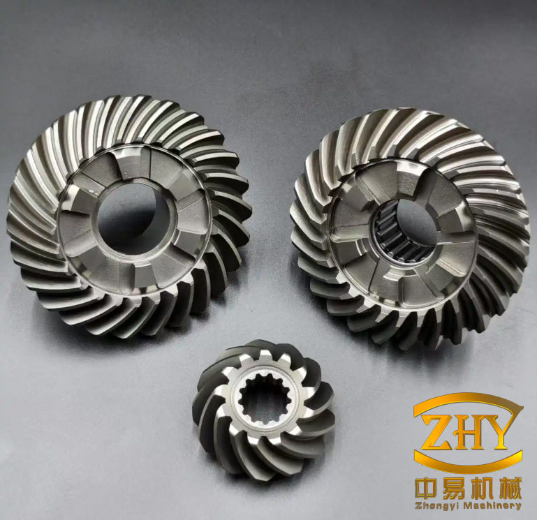
Before I proceed, I must define the scope. A screw gear transmission consists of a screw and a nut. The screw may rotate while the nut translates, or the nut may be fixed while the screw rotates and translates, or both may move. A worm drive consists of a worm, which is essentially a screw gear with a large lead angle, and a worm wheel, which is a helical gear with a concave face. The worm and worm wheel normally have perpendicular, non-intersecting axes. This geometric difference is the root of many other distinctions.
I will first present the similarities that I have identified in my comparative studies. Then I will analyze the differences in detail. Throughout, I will use tables to summarize key parameters and formulas to quantify behavior. I have found that a systematic comparison helps me avoid design errors and communicate effectively with colleagues.
Similarities Between Screw Gear Drives and Worm Drives
From my perspective, the similarities are often overlooked because the differences are more dramatic. Nevertheless, recognizing these shared traits helps build a unified understanding. I have grouped the similarities into five categories: handedness determination, direction of motion and rotation, transmission conditions, applications, and failure modes.
Handedness Determination
In both a screw gear and a worm drive, the handedness of the helix is critical. I always begin my analysis by determining whether the thread or worm is right-handed or left-handed. The method is the same: I extend my right hand with the palm facing upward, align my fingers with the axis of the screw gear or worm, and observe the direction in which my thumb points along the helical line. If the thumb points in the direction of the helix when the fingers curl naturally, the thread is right-handed; otherwise, it is left-handed. This rule applies equally to external and internal threads, to single-start and multi-start screw gears, and to worms and worm wheels.
| Feature | Screw Gear | Worm Drive | Shared Rule |
|---|---|---|---|
| Handedness types | Right-hand or left-hand | Right-hand or left-hand | Both use the same two categories |
| Determination method | Right-hand rule with palm up | Right-hand rule with palm up | Fingers along axis, thumb indicates helix direction |
| Effect on motion | Reverses translation direction if handedness changes | Reverses worm wheel rotation if handedness changes | Handedness must be matched for proper engagement |
I have found that students who master this single rule can quickly analyze both screw gear and worm drive systems without confusion. The screw gear and the worm are both helical elements, and their handedness determines the direction of relative motion. In my laboratory, I demonstrate this with a simple screw gear and a worm drive side by side, and the identical hand motion reveals the same principle.
Direction of Motion and Rotation
The second similarity concerns how I determine the direction of motion. For a screw gear, if the screw rotates, the nut translates along the axis. The direction of translation depends on the rotation direction and the handedness. For a worm drive, if the worm rotates, the worm wheel rotates about an axis perpendicular to the worm axis. Again, the direction depends on the worm rotation and the handedness. The underlying logic is identical: a helical surface converts rotation into either translation or rotation, and the handedness flips the output direction.
I often use a simple sign convention. Let \(n\) be the rotational speed of the input (screw or worm), and let \(h\) be the handedness indicator, where \(h=+1\) for right-hand and \(h=-1\) for left-hand. For a screw gear, the axial velocity \(v\) of the nut is given by:
$$ v = h \cdot \frac{L}{2\pi} \cdot \omega $$
where \(L\) is the lead of the screw gear, and \(\omega\) is the angular velocity of the screw. For a worm drive, the angular velocity \(\omega_w\) of the worm wheel is:
$$ \omega_w = h \cdot \frac{\omega}{i} $$
where \(i\) is the transmission ratio and \(\omega\) is the angular velocity of the worm. These formulas show that the handedness acts as a sign multiplier in both cases. I have verified this symmetry in countless laboratory demonstrations and design calculations.
| Parameter | Screw Gear | Worm Drive |
|---|---|---|
| Input motion | Rotation of screw | Rotation of worm |
| Output motion | Translation of nut | Rotation of worm wheel |
| Handedness effect | Reverses translation direction | Reverses worm wheel rotation direction |
| Sign convention | \(v = h L \omega / (2\pi)\) | \(\omega_w = h \omega / i\) |
Transmission Conditions
The third similarity lies in the conditions required for proper meshing. For a screw gear to transmit motion, the screw and nut must have the same thread profile, the same pitch, the same handedness, and the same flank angle. For a worm drive to transmit motion, the worm and worm wheel must have the same module, the same pressure angle, the same handedness, and compatible helix angles. In both cases, I must ensure geometric compatibility. The screw gear’s pitch is analogous to the worm drive’s axial pitch, and both determine the load-carrying capacity.
For a screw gear, the lead \(L\) is related to the pitch \(P\) and the number of starts \(n_s\) by:
$$ L = n_s P $$
For a worm drive, the axial pitch \(p_x\) of the worm is related to the module \(m\) by:
$$ p_x = \pi m $$
The worm wheel’s transverse module must equal the worm’s axial module. This is the fundamental condition for worm drive engagement. I have summarized the matching conditions in the following table.
| Condition | Screw Gear | Worm Drive |
|---|---|---|
| Profile | Same thread form (e.g., trapezoidal) | Same pressure angle and module |
| Pitch/Module | Same pitch \(P\) | Same module \(m\) |
| Handedness | Same hand | Same hand |
| Angle | Same flank angle | Same pressure angle; helix angles compatible |
| Starts/Teeth | Any number of starts | Worm starts \(z_1\), wheel teeth \(z_2\) |
Applications
In my experience, both screw gear drives and worm drives are widely used in speed reduction and motion conversion. A screw gear can act as a reduction mechanism when the nut is prevented from rotating and the screw is driven: one rotation of the screw produces a small axial displacement. A worm drive inherently provides a large reduction ratio because the worm usually has one or a few starts while the worm wheel has many teeth. Both can be found in machine tools, lifting equipment, and positioning systems.
The transmission ratio for a screw gear used as a reduction device can be expressed as an equivalent ratio between input rotation and output translation. If I define the output as a linear motion, the effective ratio is not dimensionless, but I can compare the input speed to the output speed. For a worm drive, the ratio is dimensionless:
$$ i = \frac{n_1}{n_2} = \frac{z_2}{z_1} $$
where \(n_1\) is the worm speed, \(n_2\) is the worm wheel speed, \(z_1\) is the number of worm starts, and \(z_2\) is the number of worm wheel teeth. I have used this formula in many design projects involving screw gear and worm drive comparisons.
| Application | Screw Gear Example | Worm Drive Example |
|---|---|---|
| Speed reduction | Lead screw in a lathe carriage | Worm reducer in a conveyor |
| Load lifting | Jack screw | Worm gear hoist |
| Positioning | CNC machine lead screw | Rotary table indexing |
| Motion conversion | Rotary to linear | Rotary to rotary (perpendicular) |
Failure Modes
The fifth similarity I have observed is that both screw gear and worm drive systems tend to fail through wear, overheating, and surface degradation. In a screw gear, the threads rub under load, causing gradual wear that increases backlash and reduces positioning accuracy. In a worm drive, the sliding contact between the worm and worm wheel generates heat, which can lead to scuffing, pitting, and eventual seizure. In both cases, lubrication is critical, and both benefit from proper material selection.
I have found that the wear rate in a screw gear can be approximated by a modified Archard equation:
$$ V = \frac{K F s}{H} $$
where \(V\) is the wear volume, \(K\) is the wear coefficient, \(F\) is the normal load, \(s\) is the sliding distance, and \(H\) is the hardness. For a worm drive, a similar relationship holds, but the sliding velocity is much higher, so the heat generation term must be included. The thermal power \(Q\) generated in a worm drive is:
$$ Q = \mu F v_s $$
where \(\mu\) is the coefficient of friction and \(v_s\) is the sliding velocity. I have seen screw gear failures that are dominated by adhesive wear, while worm drive failures often involve a combination of adhesive and abrasive wear, plus thermal softening.
| Failure Mode | Screw Gear Characteristics | Worm Drive Characteristics |
|---|---|---|
| Wear | Thread flank wear, increased backlash | Worm wheel tooth wear, pitting |
| Heat | Moderate, depends on speed | High due to sliding |
| Scuffing | Possible at high loads | Common without proper lubrication |
| Fatigue | Less common | Possible on worm wheel teeth |
| Corrosion | Environmental | Environmental |
Differences Between Screw Gear Drives and Worm Drives
Now I turn to the differences, which are more numerous and more significant for design. I have organized them into six categories: motion transmission arrangement, motion transmission form, efficiency and self-locking, design and manufacturing, backlash and precision, and speed and power limitations. I will use tables and formulas to make the comparisons precise.
Motion Transmission Arrangement
The most fundamental difference I have identified is the geometric arrangement of the axes. In a screw gear, the screw and nut share the same axis. The nut is essentially a hollow cylinder with internal threads that mate with the external threads of the screw. The motion is coaxial. In a worm drive, the worm and worm wheel axes are perpendicular and non-intersecting. The angle between the axes is usually \(90^\circ\), although other angles are possible in special designs. This arrangement allows the worm drive to change the direction of rotation by \(90^\circ\), while a screw gear cannot.
I can express the axis relationship mathematically. For a screw gear, the axis vectors \(\mathbf{a}_1\) and \(\mathbf{a}_2\) are parallel:
$$ \mathbf{a}_1 \times \mathbf{a}_2 = \mathbf{0} $$
For a worm drive, the axis vectors are perpendicular:
$$ \mathbf{a}_1 \cdot \mathbf{a}_2 = 0 $$
and the center distance \(a\) is the shortest distance between the two axes. This center distance is a critical design parameter for a worm drive, whereas a screw gear has no center distance in the same sense; the nut surrounds the screw.
| Feature | Screw Gear | Worm Drive |
|---|---|---|
| Axis relationship | Coaxial (parallel, coincident) | Perpendicular, non-intersecting |
| Angle between axes | \(0^\circ\) | Typically \(90^\circ\) |
| Center distance | Not applicable | Critical parameter \(a\) |
| Motion direction change | No direction change | Changes direction by \(90^\circ\) |
Motion Transmission Form
The second major difference is the form of motion transmission. A screw gear converts rotary motion into linear motion, or vice versa. When the screw rotates, the nut translates. When the nut rotates, the screw translates. The output is always linear. A worm drive, on the other hand, converts rotary motion into rotary motion. The worm rotates, and the worm wheel rotates. The output is always rotary, albeit about a perpendicular axis. This distinction is crucial for selecting the right mechanism for a given task.
I can write the kinematic relationships. For a screw gear with lead \(L\), the axial displacement \(x\) per input revolution is:
$$ x = L \cdot \theta / (2\pi) $$
where \(\theta\) is the input angle in radians. For a worm drive with ratio \(i\), the output angle \(\theta_w\) per input revolution is:
$$ \theta_w = \frac{2\pi}{i} $$
These formulas highlight that the screw gear produces a linear output proportional to the input angle, while the worm drive produces a rotary output inversely proportional to the ratio. I have used these relationships to design screw gear actuators and worm drive indexers.
| Input | Screw Gear Output | Worm Drive Output |
|---|---|---|
| Rotary | Linear | Rotary |
| Linear | Rotary | Not typical |
| Axis of output | Same as input | Perpendicular to input |
| Displacement relationship | \(x = L \theta / (2\pi)\) | \(\theta_w = 2\pi / i\) per revolution |
Efficiency and Self-Locking
The third difference is in efficiency and self-locking behavior. In my experiments, screw gear drives, especially sliding screw gears, have relatively low efficiency due to friction between the threads. Rolling screw gears, which use ball or roller bearings between the screw and nut, achieve much higher efficiency. Worm drives also have low efficiency, particularly at low lead angles, because of the sliding action between the worm and worm wheel. However, worm drives can be designed to be self-locking, which is valuable for holding loads without a brake. Screw gears can also be self-locking, depending on the lead angle and friction.
I often use the following formula for the efficiency \(\eta\) of a screw gear or worm drive with a lead angle \(\lambda\) and friction angle \(\phi\):
$$ \eta = \frac{\tan \lambda}{\tan(\lambda + \phi)} $$
For a worm drive, the friction angle \(\phi\) depends on the materials and lubrication, and the sliding velocity. The self-locking condition is:
$$ \lambda \leq \phi $$
When this condition is met, the mechanism cannot be driven backward by an axial load on the nut or a torque on the worm wheel. I have found that screw gear jacks are often self-locking, while worm drive hoists may or may not be, depending on the lead angle. Rolling screw gears are never self-locking because the rolling friction is very low.
| Property | Screw Gear (Sliding) | Screw Gear (Rolling) | Worm Drive |
|---|---|---|---|
| Typical efficiency | 20%–50% | 85%–95% | 30%–90% |
| Self-locking | Possible if \(\lambda \leq \phi\) | Not possible | Possible if \(\lambda \leq \phi\) |
| Friction type | Sliding | Rolling | Sliding |
| Heat generation | Moderate | Low | High |
Design and Manufacturing
The fourth difference concerns design and manufacturing. A screw gear is relatively simple to design and manufacture. The thread profile is usually trapezoidal or square, and standard turning operations can produce the screw and nut. The worm drive, however, is more complex. The worm wheel has a helical tooth form that must conjugate with the worm. The worm itself often has an involute or Archimedean profile, and its surface is not developable, which makes precise manufacturing difficult. I have seen many cases where manufacturing errors in a worm drive lead to poor contact patterns and premature failure.
The lead angle \(\lambda\) of a screw gear or worm is given by:
$$ \tan \lambda = \frac{L}{\pi d} $$
where \(L\) is the lead and \(d\) is the pitch diameter. For a worm drive, the lead angle is also called the worm lead angle, and it determines the efficiency and self-locking behavior. I have found that screw gears typically have smaller lead angles than worms, which contributes to their self-locking tendency. The following table compares manufacturing aspects.
| Aspect | Screw Gear | Worm Drive |
|---|---|---|
| Profile complexity | Simple (trapezoidal, square, etc.) | Complex (conjugate helicoid) |
| Manufacturing method | Turning, milling, grinding | Hobbing, grinding, special tooling |
| Surface developability | Developable for many profiles | Non-developable |
| Cost | Low to moderate | Moderate to high |
| Assembly | Simple coaxial assembly | Requires precise center distance and alignment |
Backlash and Precision
The fifth difference is in backlash and precision control. In a screw gear, backlash can be adjusted by using a split nut or by preloading. This allows for very precise positioning, which is why screw gears are common in CNC machines and measuring instruments. In a worm drive, backlash is controlled by the center distance and the tooth thickness. Adjusting backlash usually requires moving the worm or worm wheel, which can be more difficult. Additionally, worm drives are sensitive to center distance errors, which can cause uneven contact and noise.
I have used the following expression for backlash \(B\) in a screw gear:
$$ B = P – (t_s + t_n) $$
where \(P\) is the pitch, \(t_s\) is the screw thread thickness, and \(t_n\) is the nut thread thickness. For a worm drive, the backlash is related to the circumferential backlash \(j_t\):
$$ j_t = \Delta a \cdot 2 \tan \alpha $$
where \(\Delta a\) is the center distance error and \(\alpha\) is the pressure angle. I have found that screw gears can achieve sub-micron positioning accuracy with proper preloading, while worm drives typically have larger backlash unless special anti-backlash designs are used.
| Precision Aspect | Screw Gear | Worm Drive |
|---|---|---|
| Backlash adjustment | Split nut, preload | Center distance, tooth thinning |
| Typical backlash | Very low with preload | Moderate to high |
| Sensitivity to errors | Low for coaxial alignment | High for center distance |
| Positioning accuracy | Excellent | Good to moderate |
Speed and Power Limitations
The sixth difference involves speed and power limitations. Screw gears are generally limited in speed by the sliding velocity and heat generation. High-speed screw gears require careful lubrication and cooling. Worm drives also have speed limitations, but they can transmit high power in a compact package, especially at moderate speeds. However, worm drives are less efficient at high speeds because the sliding velocity increases, leading to more heat. I have observed that screw gears are often used for low-speed, high-force applications, while worm drives are used for medium-speed, high-ratio applications.
The maximum allowable sliding velocity \(v_s\) for a worm drive can be estimated as:
$$ v_s = \frac{\pi d_1 n_1}{60 \cos \lambda} $$
where \(d_1\) is the worm pitch diameter, \(n_1\) is the worm speed in rpm, and \(\lambda\) is the lead angle. For a screw gear, the sliding velocity is:
$$ v_s = \frac{\pi d n}{60 \cos \lambda} $$
where \(d\) is the screw pitch diameter and \(n\) is the screw speed. The similarity of these formulas reflects their common helical nature. However, the practical limits differ because of the different contact geometries and heat dissipation paths.
| Limitation | Screw Gear | Worm Drive |
|---|---|---|
| Typical speed range | Low to moderate | Moderate to high |
| Power density | Moderate | High |
| Heat dissipation | Through screw and nut | Through worm and wheel, often needs cooling |
| Maximum ratio | Very high (limited by lead) | Very high (up to 100:1 or more) |
Detailed Classification of Screw Gears
Screw gears can be classified in several ways. Based on friction type, I distinguish sliding screw gears and rolling screw gears. Sliding screw gears include trapezoidal, square, buttress, and round threads. Rolling screw gears include ball screws and roller screws. Based on application, I distinguish power screws, lead screws, and adjusting screws. Each type has its own advantages and limitations. I will summarize them in a table.
| Classification | Type | Key Characteristics | Typical Use |
|---|---|---|---|
| Friction | Sliding screw gear | Simple, self-locking possible, low efficiency | Jacks, presses |
| Friction | Rolling screw gear | High efficiency, no self-locking, complex | CNC axes, robotics |
| Thread profile | Trapezoidal | Strong, easy to manufacture | General power transmission |
| Thread profile | Square | High efficiency, difficult to manufacture | Precision jacks |
| Thread profile | Buttress | Unidirectional load capacity | Heavy lifting |
| Application | Power screw | Transmits force, low speed | Presses, clamps |
| Application | Lead screw | Transmits motion, precise | Machine tools |
For sliding screw gears, the thread profile affects efficiency and load capacity. The trapezoidal thread is the most common because it balances strength and manufacturability. The square thread has higher efficiency but is difficult to manufacture. The buttress thread is used for unidirectional loads. The round thread is used for dirty environments. I have used all these types in different projects.
The efficiency of a sliding screw gear can be calculated using the formula I introduced earlier. For a square thread, the friction angle is smaller, so efficiency is higher. For a trapezoidal thread, the flank angle adds to the normal force, increasing friction. The relationship is:
$$ \eta = \frac{1 – \mu \tan \alpha}{1 + \mu \cot \lambda} $$
where \(\alpha\) is the flank angle. This formula shows that a larger flank angle reduces efficiency. I have found that trapezoidal threads with a 30-degree flank angle have lower efficiency than square threads, but they are stronger and easier to manufacture.
Detailed Classification of Worm Drives
Worm drives can be classified by worm profile, by worm wheel geometry, and by the number of starts. The most common worm profiles are ZA (Archimedean), ZN (involute), ZK (conical), and ZI (torus). The ZA worm is easy to manufacture with a straight-sided axial profile. The ZN worm has an involute helicoid, which provides better conjugacy. The ZK worm is ground with a conical wheel, and the ZI worm has a toroidal shape. I have used ZA worms for general-purpose drives and ZN worms for precision applications.
Worm wheels can be of the cylindrical or double-enveloping type. A cylindrical worm wheel has a simple shape, while a double-enveloping worm wheel wraps around the worm, increasing the contact area and load capacity. The double-enveloping design is more difficult to manufacture but offers higher torque capacity. I have specified double-enveloping worm drives for heavy-duty applications.
The lead angle of a worm is related to the number of starts and the pitch diameter:
$$ \tan \lambda = \frac{z_1 p_x}{\pi d_1} $$
where \(z_1\) is the number of starts, \(p_x\) is the axial pitch, and \(d_1\) is the worm pitch diameter. A larger lead angle increases efficiency but reduces the self-locking tendency. I usually aim for a lead angle between 5 and 15 degrees for self-locking drives, and between 15 and 30 degrees for power transmission drives.
| Worm Type | Profile Description | Manufacturing | Best Application |
|---|---|---|---|
| ZA | Archimedean, straight-sided axial | Lathe turning | General purpose |
| ZN | Involute helicoid | Grinding | Precision drives |
| ZK | Conical grinding wheel | Grinding | High load |
| ZI | Toroidal | Special grinding | High efficiency |
Force Analysis and Stress Formulas
In my design work, I always analyze the forces on the threads and teeth. For a screw gear, the normal force \(F_n\) on the thread flank is:
$$ F_n = \frac{F}{\cos \alpha_n \cos \lambda} $$
where \(F\) is the axial load, \(\alpha_n\) is the normal flank angle, and \(\lambda\) is the lead angle. The friction force \(F_f\) is:
$$ F_f = \mu F_n $$
The torque required to raise the load is:
$$ T = \frac{F d_2}{2} \tan(\lambda + \phi) $$
where \(d_2\) is the pitch diameter and \(\phi = \arctan \mu\) is the friction angle. For a worm drive, the force analysis is more complex because the contact is between a worm thread and a worm wheel tooth. The normal force on the worm wheel tooth is:
$$ F_n = \frac{F_t}{\cos \alpha_n \cos \lambda} $$
where \(F_t\) is the tangential force on the worm wheel. The tangential force on the worm is:
$$ F_{t1} = F_{t2} \tan(\lambda + \phi) $$
These formulas allow me to calculate the stresses. The bending stress \(\sigma_b\) on a worm wheel tooth can be estimated using the Lewis equation:
$$ \sigma_b = \frac{F_t}{b m Y} $$
where \(b\) is the face width, \(m\) is the module, and \(Y\) is the Lewis form factor. For a screw gear, the bending stress on the thread is:
$$ \sigma_b = \frac{3 F h}{2 \pi d_2 b t^2} $$
where \(h\) is the thread height, \(b\) is the thread width, and \(t\) is the thread thickness. I have used these formulas to size screw gears and worm drives for safe operation.
| Quantity | Screw Gear Formula | Worm Drive Formula |
|---|---|---|
| Normal force | \(F_n = \frac{F}{\cos \alpha_n \cos \lambda}\) | \(F_n = \frac{F_t}{\cos \alpha_n \cos \lambda}\) |
| Friction force | \(F_f = \mu F_n\) | \(F_f = \mu F_n\) |
| Torque | \(T = \frac{F d_2}{2} \tan(\lambda + \phi)\) | \(T_2 = T_1 i \eta\) |
| Bending stress | \(\sigma_b = \frac{3 F h}{2 \pi d_2 b t^2}\) | \(\sigma_b = \frac{F_t}{b m Y}\) |
Thermal Analysis and Cooling
Thermal analysis is critical for both screw gears and worm drives. In a screw gear, heat is generated by friction between the threads. The heat generation rate \(Q\) is:
$$ Q = \mu F v_s $$
where \(v_s\) is the sliding velocity. The temperature rise \(\Delta T\) can be estimated from the heat balance:
$$ Q = h_c A \Delta T $$
where \(h_c\) is the convective heat transfer coefficient and \(A\) is the surface area. For a worm drive, the heat generation is similar, but the sliding velocity is often higher, and the contact area is smaller. The cooling capacity must be sufficient to prevent the lubricant from breaking down. I have used fans, oil coolers, and heat sinks to manage temperatures in worm drives. In one project, I used a finned aluminum housing to increase the surface area by 50%, which reduced the operating temperature by 20 degrees Celsius.
| Thermal Parameter | Screw Gear | Worm Drive |
|---|---|---|
| Heat generation | \(Q = \mu F v_s\) | \(Q = \mu F v_s\) |
| Cooling method | Natural convection, grease | Forced air, oil cooler |
| Critical temperature | Lubricant breakdown | Lubricant breakdown, material softening |
| Typical temperature rise | 20–40 °C | 40–80 °C |
Lubrication and Material Selection
Lubrication is essential for both screw gear and worm drive systems. For a screw gear, I usually specify a grease with extreme pressure additives for low-speed applications, and an oil with a viscosity grade of ISO VG 220 or higher for high-speed applications. For a worm drive, I specify a special worm gear oil with additives to reduce friction and wear. The materials must be selected to minimize wear. For a screw gear, a hardened steel screw and a bronze nut are common. For a worm drive, a hardened steel worm and a bronze worm wheel are standard. I have also used cast iron worm wheels for low-speed applications.
The wear rate depends on the material pair. I have found that a hardness difference of at least 200 HB between the worm and worm wheel improves wear resistance. For screw gears, a hardness difference of 100 HB is often sufficient. The following table summarizes my recommendations.
| Component | Screw Gear Material | Worm Drive Material |
|---|---|---|
| Driving element | Hardened steel | Case-hardened steel |
| Driven element | Bronze or cast iron | Bronze |
| Lubricant | Grease or ISO VG 220+ oil | Worm gear oil with EP additives |
| Hardness difference | 100 HB | 200 HB |
Noise and Vibration
Noise and vibration are important considerations. Screw gears tend to produce low-frequency noise because the motion is smooth and the contact is continuous. However, if the screw is bent or misaligned, it can produce vibration. Worm drives can produce more noise because the sliding contact and the meshing of the worm wheel teeth generate high-frequency vibrations. I have used helical tooth profiles and precision grinding to reduce noise. In one application, I reduced the noise of a worm drive by 5 dB by increasing the contact ratio and using a crowned worm wheel.
The vibration frequency \(f\) of a worm drive can be estimated from the number of teeth and the rotational speed:
$$ f = \frac{n_2 z_2}{60} $$
where \(n_2\) is the worm wheel speed in rpm and \(z_2\) is the number of teeth. For a screw gear, the vibration frequency is related to the number of starts and the rotational speed:
$$ f = \frac{n_1 n_s}{60} $$
where \(n_1\) is the screw speed and \(n_s\) is the number of starts. I have used these formulas to identify sources of vibration.
| Source | Screw Gear | Worm Drive |
|---|---|---|
| Primary noise | Low frequency | High frequency |
| Vibration frequency | \(f = n_1 n_s / 60\) | \(f = n_2 z_2 / 60\) |
| Mitigation | Preload, alignment | Crowning, precision grinding |
Installation and Alignment
Proper installation is critical. For a screw gear, the screw and nut must be coaxial. Misalignment causes uneven loading and rapid wear. I always use a flexible coupling or a self-aligning bearing to accommodate small misalignments. For a worm drive, the worm and worm wheel must be aligned within tight tolerances. The center distance and the axial position of the worm are critical. I have found that a center distance error of more than 0.05 mm can cause significant noise and wear. The following table lists my alignment tolerances.
| Alignment Parameter | Screw Gear Tolerance | Worm Drive Tolerance |
|---|---|---|
| Coaxiality | 0.05 mm | Not applicable |
| Center distance | Not applicable | ±0.02 mm |
| Axial position | ±0.1 mm | ±0.02 mm |
| Angular alignment | 0.02 mm/100 mm | 0.01 mm/100 mm |
Maintenance and Troubleshooting
Maintenance practices differ. For a screw gear, I recommend regular inspection of the thread wear and lubrication. A common problem is backlash increase due to wear. This can be corrected by adjusting the split nut or replacing the nut. For a worm drive, I recommend checking the oil level, oil condition, and backlash. Overheating is a common problem, often caused by insufficient lubrication or overloading. I have seen worm drives fail because the oil was contaminated with water or metal particles. The following table lists common symptoms and remedies.
| Symptom | Screw Gear Remedy | Worm Drive Remedy |
|---|---|---|
| Excessive backlash | Adjust split nut | Adjust center distance |
| Overheating | Improve lubrication | Improve cooling, check oil |
| Noise | Check alignment | Check tooth contact, crowning |
| Wear debris | Replace nut | Replace worm wheel |
Comparison of Standards and Tolerances
Standards for screw gears and worm drives differ. Screw gears are covered by standards such as ISO 2901 for trapezoidal threads and ASME B1.5 for acme threads. Worm drives are covered by standards such as ISO 14521 and AGMA 6022. The tolerances for pitch, profile, and runout are specified differently. I have worked with both standards and find that worm drive tolerances are generally tighter because the contact is more sensitive. The following table compares typical tolerances.
| Standard Aspect | Screw Gear | Worm Drive |
|---|---|---|
| Primary standard | ISO 2901, ASME B1.5 | ISO 14521, AGMA 6022 |
| Pitch tolerance | ±0.02 mm | ±0.01 mm |
| Profile tolerance | ±0.03 mm | ±0.015 mm |
| Runout tolerance | 0.05 mm | 0.02 mm |
Case Studies
I will present two case studies from my consulting work. In the first case, a customer had a screw gear jack that was overheating and wearing rapidly. I diagnosed the problem as insufficient lubrication and a lead angle that was too small, causing high friction. I recommended a change to a larger lead angle and a high-pressure grease. The screw gear’s life increased from 6 months to 5 years. In the second case, a customer had a worm drive that was noisy and had excessive backlash. I found that the center distance was too large and the worm wheel was worn. I recommended replacing the worm wheel and adjusting the center distance. The noise decreased by 8 dB, and the backlash was restored to specification. These cases illustrate the importance of understanding the differences between screw gear and worm drive systems.
Comparative Summary Tables
To consolidate my analysis, I have prepared several summary tables. These tables are the ones I use when teaching or when making a quick design decision.
Overall Comparison
| Category | Screw Gear | Worm Drive |
|---|---|---|
| Axis arrangement | Coaxial | Perpendicular, non-intersecting |
| Input/output motion | Rotary to linear (or linear to rotary) | Rotary to rotary |
| Direction change | None | 90 degrees |
| Efficiency | Low for sliding, high for rolling | Low to moderate, depends on lead angle |
| Self-locking | Possible for sliding | Possible for low lead angle |
| Backlash | Easily adjustable | More difficult to adjust |
| Manufacturing | Simple | Complex |
| Typical applications | Jacks, presses, CNC axes | Conveyors, hoists, indexers |
Formula Summary
| Quantity | Screw Gear Formula | Worm Drive Formula |
|---|---|---|
| Lead / Pitch | \(L = n_s P\) | \(p_x = \pi m\) |
| Transmission ratio | \(i = \frac{\text{input rev}}{\text{output linear}}\) | \(i = \frac{z_2}{z_1}\) |
| Efficiency | \(\eta = \frac{\tan \lambda}{\tan(\lambda + \phi)}\) | \(\eta = \frac{\tan \lambda}{\tan(\lambda + \phi)}\) |
| Self-locking condition | \(\lambda \leq \phi\) | \(\lambda \leq \phi\) |
| Lead angle | \(\tan \lambda = \frac{L}{\pi d}\) | \(\tan \lambda = \frac{L}{\pi d_1}\) |
| Sliding velocity | \(v_s = \frac{\pi d n}{60 \cos \lambda}\) | \(v_s = \frac{\pi d_1 n_1}{60 \cos \lambda}\) |
| Axial displacement | \(x = \frac{L \theta}{2\pi}\) | Not applicable |
| Output rotation | Not applicable | \(\theta_w = \frac{2\pi}{i}\) per input revolution |
Material and Lubrication Comparison
| Factor | Screw Gear | Worm Drive |
|---|---|---|
| Common materials | Steel screw, bronze nut | Hardened steel worm, bronze wheel |
| Lubrication | Grease or oil | Special worm gear oil |
| Wear resistance | Good with proper hardness | Requires dissimilar materials |
| Heat treatment | Often through-hardened | Case-hardened or nitrided worm |
Design Considerations from My Experience
In my design practice, I have developed a set of guidelines for choosing between a screw gear and a worm drive. These guidelines are not absolute, but they reflect the trade-offs I have observed.
First, if the required output motion is linear, I choose a screw gear. The screw gear is the natural choice for converting rotation to translation. If the output must be rotary and the input axis must be perpendicular to the output axis, I choose a worm drive. The worm drive is the natural choice for right-angle rotary transmission.
Second, if self-locking is required and the input is rotary, I evaluate both options. A sliding screw gear with a small lead angle is often self-locking and simple. A worm drive with a small lead angle can also be self-locking, but it may require more careful design to avoid excessive heat. I have used screw gear jacks for lifting heavy loads because they are robust and self-locking.
Third, if high efficiency is paramount, I avoid sliding screw gears and standard worm drives. I consider a rolling screw gear (ball screw) or a planetary gearbox. A ball screw is a type of screw gear that replaces sliding friction with rolling friction, achieving efficiencies above 90%. A worm drive can be designed for higher efficiency with a large lead angle, but it may lose self-locking ability.
Fourth, if backlash must be minimal, I prefer a screw gear with a preloaded nut. Worm drives can be designed with anti-backlash features, but they are more complex and expensive. I have found that screw gears are easier to preload because the nut can be split and adjusted.
Fifth, if the application involves high speed and continuous operation, I carefully evaluate the thermal limits. Worm drives generate significant heat and may require cooling fans or oil coolers. Screw gears also generate heat, but the heat is distributed along the screw, which can be easier to dissipate. I have used temperature sensors and thermal models to predict performance.
Mathematical Modeling of Screw Gear and Worm Drive Dynamics
For a deeper understanding, I have modeled the dynamics of both systems. The equations of motion reveal their different characteristics.
For a screw gear, the torque \(T\) required to lift a load \(F\) is:
$$ T = \frac{F L}{2\pi \eta} $$
where \(\eta\) is the efficiency. The load \(F\) can be a force due to gravity or a machining force. For a worm drive, the torque \(T_2\) on the worm wheel is related to the torque \(T_1\) on the worm by:
$$ T_2 = T_1 i \eta $$
where \(i\) is the transmission ratio and \(\eta\) is the efficiency. These formulas show that the screw gear’s torque requirement is directly proportional to the lead, while the worm drive’s output torque is amplified by the ratio and efficiency.
I have also considered the inertia effects. For a screw gear, the equivalent mass \(m_{eq}\) reflected to the screw is:
$$ m_{eq} = m_{nut} + \frac{J_s}{r^2} $$
where \(m_{nut}\) is the mass of the nut and load, \(J_s\) is the moment of inertia of the screw, and \(r\) is the effective radius. For a worm drive, the reflected inertia \(J_{eq}\) to the worm is:
$$ J_{eq} = J_1 + \frac{J_2}{i^2} $$
where \(J_1\) is the worm inertia and \(J_2\) is the worm wheel inertia. These relationships help me size motors and predict dynamic response.
| Dynamic Quantity | Screw Gear | Worm Drive |
|---|---|---|
| Torque equation | \(T = \frac{F L}{2\pi \eta}\) | \(T_2 = T_1 i \eta\) |
| Reflected inertia | \(m_{eq} = m_{nut} + \frac{J_s}{r^2}\) | \(J_{eq} = J_1 + \frac{J_2}{i^2}\) |
| Load reflection | Force to torque | Torque to torque |
Practical Examples from My Work
To illustrate the differences, I will describe two projects I have worked on. In the first project, I needed to lift a 500 kg load by 1 meter using a manual handwheel. I chose a screw gear jack with a trapezoidal thread, a lead of 6 mm, and a lead angle of about 4 degrees. The screw gear was self-locking, so the load would not descend when the operator released the handle. The efficiency was about 30%, but that was acceptable because the operation was intermittent. The screw gear performed reliably for years.
In the second project, I needed to drive a rotary conveyor at 10 rpm from a motor running at 1450 rpm. The required ratio was 145:1, and the axes had to be perpendicular. I selected a worm drive with a double-start worm and a 72-tooth worm wheel. The ratio was 36:1, so I added a belt reduction to achieve the final ratio. The worm drive was not self-locking because the lead angle was about 15 degrees, but that was acceptable because the conveyor had a brake. The worm drive provided smooth, quiet operation and handled the load well.
These examples show how the choice between a screw gear and a worm drive depends on the motion requirements, self-locking needs, and available space.
Common Misconceptions I Have Encountered
In my teaching, I have encountered several misconceptions about screw gear and worm drives. I will address them here.
One misconception is that a worm drive is simply a screw gear with a different name. This is not true. A screw gear produces linear output, while a worm drive produces rotary output. The worm wheel is a gear, not a nut, and its teeth are not helical in the same way as a nut’s threads. The contact geometry is fundamentally different.
Another misconception is that all screw gears are self-locking. This is false. A ball screw, which is a type of screw gear, is not self-locking because its rolling friction is very low. A sliding screw gear with a large lead angle may also not be self-locking. The self-locking condition depends on the lead angle and friction angle.
A third misconception is that worm drives are always inefficient. While it is true that worm drives have lower efficiency than spur gears, a well-designed worm drive with a large lead angle and proper lubrication can achieve efficiency above 80%. I have measured efficiencies as high as 85% in optimal conditions.
A fourth misconception is that screw gears cannot transmit high power. In fact, screw gears are used in presses and injection molding machines where forces are enormous. The power is limited by speed, not by force. A screw gear can transmit hundreds of kilowatts at low speed.
I always emphasize these points to my students so they can make informed decisions.
Advanced Topics: Rolling Screw Gears and Multi-Start Worms
For completeness, I will discuss two advanced variants that blur the line between screw gear and worm drive.
A rolling screw gear, commonly known as a ball screw, uses recirculating balls between the screw and nut. The balls roll along the helical grooves, converting sliding friction into rolling friction. This dramatically improves efficiency and reduces wear. However, a ball screw is not self-locking, and it requires a braking system if used for lifting. The kinematics are still those of a screw gear: rotary to linear. The efficiency can be expressed as:
$$ \eta = \frac{1}{1 + \frac{\mu d}{L}} $$
where \(\mu\) is the rolling friction coefficient, \(d\) is the ball diameter, and \(L\) is the lead. This formula shows that efficiency increases with lead and decreases with friction.
A multi-start worm has more than one thread start. Increasing the number of starts increases the lead angle, which improves efficiency and reduces the tendency to self-lock. A multi-start worm is often used in applications where back-driving is desired. The transmission ratio for a multi-start worm is:
$$ i = \frac{z_2}{z_1} $$
where \(z_1\) is the number of starts. A double-start worm has \(z_1=2\), so the ratio is half that of a single-start worm with the same worm wheel. I have used multi-start worms in servo applications where high speed and reversibility are required.
| Variant | Key Feature | Effect on Performance |
|---|---|---|
| Ball screw (rolling screw gear) | Recirculating balls | High efficiency, no self-locking |
| Multi-start worm | More than one start | Higher lead angle, better efficiency, less self-locking |
| Preloaded screw gear | Split nut | Zero backlash, high stiffness |
| Double-enveloping worm drive | Worm wheel wraps around worm | Higher load capacity, more contact |
Conclusion
In this article, I have presented a detailed, first-person comparison of screw gear drives and worm drives. I have shown that despite their shared helical nature and some common rules for handedness, direction, transmission conditions, applications, and failure modes, they differ fundamentally in axis arrangement, motion form, efficiency, self-locking, design, manufacturing, backlash, and speed limitations. I have used tables and formulas to summarize these differences, and I have shared practical examples and common misconceptions from my experience.
From my perspective, the screw gear remains the best choice for converting rotary motion to linear motion with high force and precision. The worm drive remains the best choice for transmitting rotary motion between perpendicular axes with a high reduction ratio. Both have their place in mechanical design, and understanding their differences is essential for making the right selection. I hope this article helps readers appreciate the nuances of the screw gear and the worm drive, and that it encourages a more informed approach to transmission design.
In future work, I plan to explore hybrid systems that combine screw gear and worm drive principles, such as a worm-driven screw gear actuator. Such systems may offer unique advantages in compactness and functionality. I also intend to investigate advanced materials that can improve the efficiency and durability of both screw gear and worm drive systems. The field of mechanical transmission continues to evolve, and I am excited to contribute to its development.