
In order to further verify the correctness of the analysis on the influence of grinding wheel position deviation on the profile of cylindrical gear, the machining simulation software VERICUT is used to simulate the profile grinding of cylindrical gear. The simulation is based on a CNC profile grinding machine for linear gear, and its structure is shown in Figure 1. When grinding, the forming wheel is driven by the spindle and rotates around its own axis at high speed, while the gear to be machined rotates around axis A. After adjusting the installation position of grinding wheel and linear gear, a-axis and X-axis are linked to realize spiral motion and grinding between grinding wheel and linear gear to be machined. The linkage relationship between a-axis and x-axis is as follows:
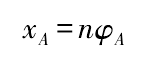
Where: XA is the feed rate of the gear to be machined along the x-axis direction; n is the pitch of the contact line; and φ A is the angle of the gear to be machined around the a-axis.

According to the principle of cylindrical linear gear form grinding, the NC machining program is compiled. Then the model of linear gear form grinding machine, the model of form grinding wheel and the NC machining program are imported into VERICUT software at the same time for grinding simulation. The process of VERICUT grinding simulation is shown in Figure 2. After simulation, the cylindrical gear model after grinding can be obtained, as shown in Figure 3.

In machining simulation, if the position deviation of grinding wheel is not considered, the theoretical tooth profile of cylindrical gear can be obtained; if different position deviation of grinding wheel is set, the error Tooth Profile of grinding wheel with position deviation can be obtained. By comparing the theoretical tooth profile with the error Tooth profile, the correctness of the error analysis can be verified.

The grinding simulation of the cylindrical gear in the example is carried out, and the comparison results between the theoretical tooth surface and the error tooth surface are obtained, as shown in Figure 4.

The axial error of the grinding wheel center along the Z2 axis is set to be 0.20 mm in the machining process, and the error tooth surface is obtained when the axial offset of the grinding wheel center along the Z2 axis is Δ SZ = 0.20 mm. At the same time, the theoretical tooth surface is imported as the design point, and the axial error Δ SZ = 0.20 mm is obtained by using the automatic comparison function of the analysis tool The comparison results between the theoretical tooth surface and the error tooth surface (see FIG. 4A). It can be seen from FIG. 4A that the tooth thickness of the cylindrical gear along the tooth height direction increases after grinding, and the tooth profile change law is consistent with the analysis results. Then through the function of blank and design distance in the measuring tool, the meshing points on the contact line of grinding tooth surface are selected for measurement, and the tooth profile error at the meshing points is 0.195 mm, which is less than 2.5% from the calculated tooth profile error at the meshing points.
Set the angle error of the grinding wheel axis rotating around the X2 axis as – 0.01 ° in the process of machining, and get the error tooth surface when the inclination error Δ α = – 0.01 ° exists in the grinding wheel axis. At the same time, import the theoretical tooth surface as the design point, and use the automatic comparison function in the analysis tool to get the comparison results between the theoretical tooth surface and the error tooth surface when the inclination error Δ α = – 0.01 ° (see Fig. 4b). It can be seen from Fig. 4B that the tooth thickness along the tooth height direction decreases after grinding, and the tooth profile change law is consistent with the analysis results. Then through the function of blank and design distance in the measuring tool, the meshing points on the contact line of grinding tooth surface are selected for measurement. The tooth profile error at the meshing points is 0.013 mm, and the deviation from the calculated tooth profile error at the meshing points is 8.33%.
To sum up, through the analysis of the listed simulation examples, it can be judged that the analysis results are reliable.