The die drawing process of spiral bevel gear precision forging is simulated in DEFORM-3D. The specific simulation process is as follows:
1.Set the motion of the upper die after the forging of simulated spiral bevel gear, including the motion along the axis and the rotation along the axis, estimate it by using the relationship between the midpoint helix angle and the tooth profile height, and set the axial motion speed and the rotation speed along the axis.
2.Set constraints on the bottom surface of spiral bevel gear forgings, which will prevent the forging from moving and rotating along the axial direction, so as to facilitate the separation from the upper die.
3.Other settings are similar to the forging process. The finite element file is generated for simulation. The process is shown in Figure 1.
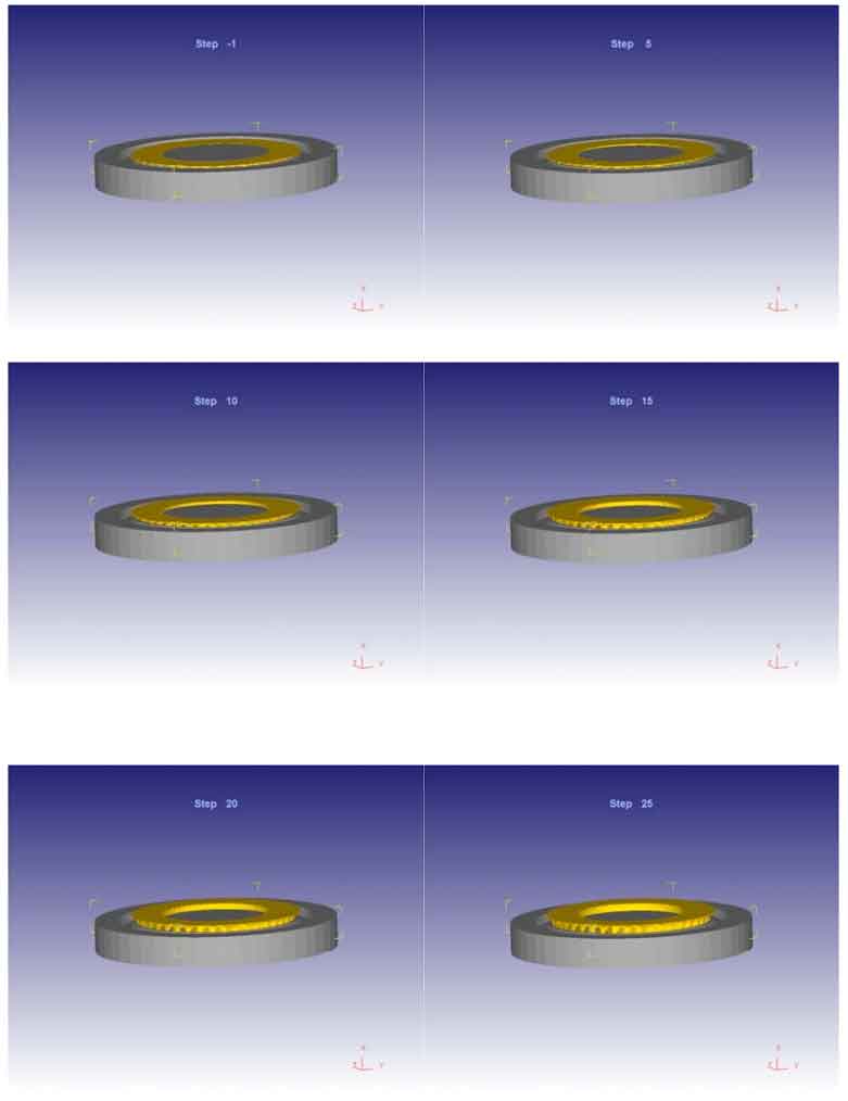
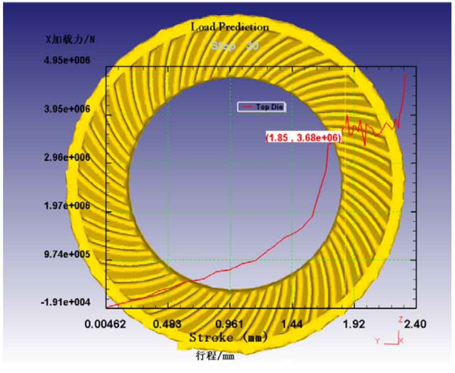
Figure 1 shows the die drawing process of spiral bevel gear precision forging. In order to clearly observe the separation process between the upper die and the workpiece, the lower die is hidden. During the separation process between the workpiece and the upper die, the loading force of the upper die and the force between the upper die and the forging are mutual forces. It can be seen from the figure that at the beginning, due to the friction between the workpiece and the upper die, The workpiece moves with the movement of the upper die, and then the workpiece is separated from the upper die. Due to the longitudinal flash at the edge of the spiral bevel gear, the tooth shape of this part changes slightly, but on the whole, the change is very small, which has little impact on the accuracy, and this part needs to be chamfered. From the image, the die drawing process of the precision forging of spiral bevel gear can be completed.
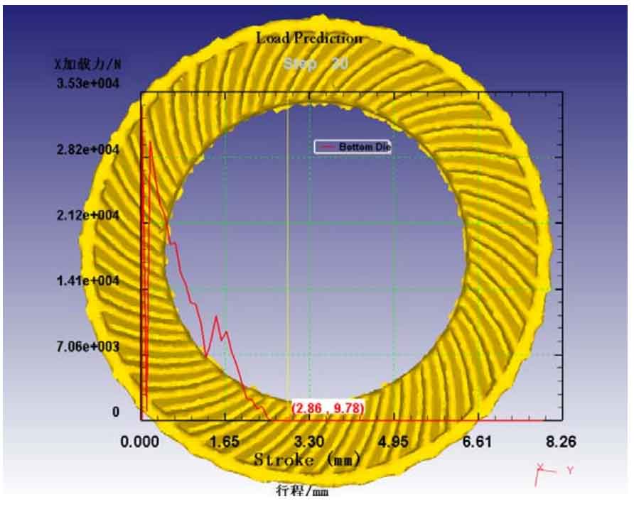
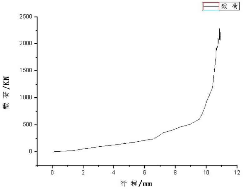
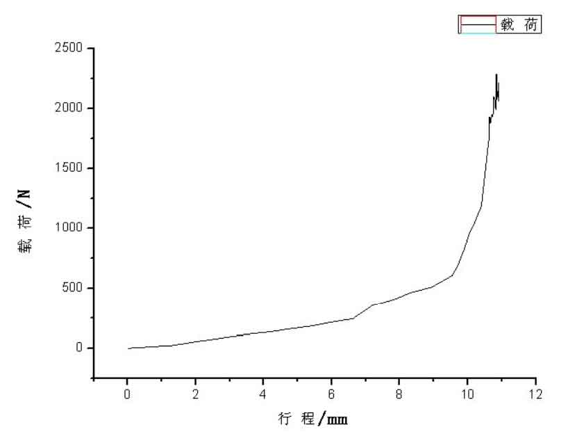
The large wheel of spiral bevel gear adopts the direct die drawing method. The stroke load curve of the workpiece in this process is shown in Figure 2. The die drawing force is small, which is only one hundredth of that of the large wheel. From this part, the die drawing process is also feasible, because the pitch cone angle of the large wheel is relatively large and the interference between the die and the forging is less in the axial direction, As long as the friction between the forging and the die is overcome, the die can be produced. The small wheel uses the spiral die out mode, and the stroke load curve is shown in Figure 3. The die out force is large, which is about 1 / 10 of that during forging; Therefore, the tooth profile of the small wheel will be seriously damaged. Therefore, under this condition, the large spiral bevel gear wheel can be successfully molded, and the small spiral bevel gear wheel cannot be molded.