
comparison analysis of tooth surface generated by face gear shaper method and tooth surface generated by gear shaper method
Calculate the difference between the tooth surface obtained from the vehicle tooth and the theoretical tooth surface based on the coordinates of the discrete points on the two tooth surfacesThe discrete point error of the tooth surface is defined as the normal distance between two tooth surfaces in this topic.When calculating the coordinates of the discrete points on the tooth surface,The grid of the two tooth surfaces is divided into the same number of rows and columns, so that the coordinates of the discrete points generated on the tooth surfaces remain in the data formatConsistency is convenient for error comparison.
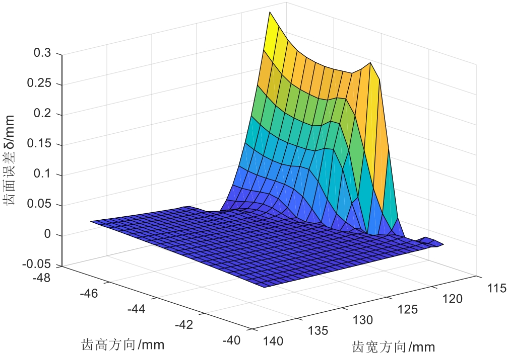
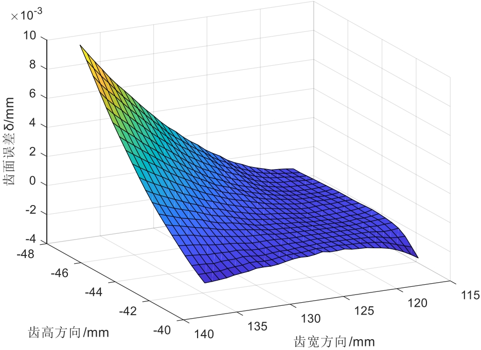
The tooth surface errors of discrete points on the concave and convex surfaces of a helical tooth surface gear are shown in Figure 2.19.On the concave surface, the working tooth surfaceMost of the discrete points basically fluctuate around 0, and there is a certain amount of undercutting in the transition tooth surface, resulting in significant errors.On the surface, the error range of the tooth surface of the discrete points is between -0.001 and 0.010 mm. According to the tooth machining method, the tooth surface and theoretical tooth profile are basically in line with each other.In terms of surface error comparison, the main error exists on the concave surface.The working tooth surface is basically completely coincident, and the transition tooth surface is attachedRecently, there has been a phenomenon of undercutting, resulting in large errors in the entire concave surface.Therefore, when machining a face gear using the lathing method, the tool should be repairedShape processing to avoid undercutting as much as possible.Through the analysis and comparison of the errors on the two tooth surfaces, it can be preliminarily verified that the tooth isCorrectness of gear tooth processing for spiral tooth surface gears.
3D modeling of helical tooth surface gear
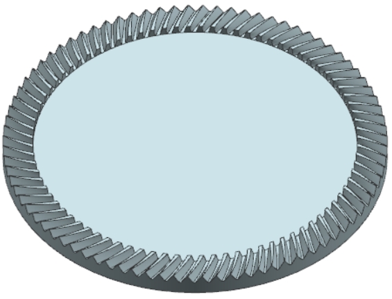
Import the obtained discrete point coordinate file of the helical tooth surface gear into Pro/E for 3D forming processing.The process of generating helical tooth surfaces with gear shapers is the same as that of gear shapers, and this article will not go into detail here. The helical tooth surfaces obtained by gear shapers areThe 3D model of the face gear is shown in the figure.
Taking the meshing of involute cylindrical gears and helical tooth gears as an example, based on the gear shaving principle of helical tooth gears, a model is established.The tooth surface equation of cylindrical gears was established, and the theoretical tooth surface equation of helical tooth surface gears was derived based on the principle of spatial gear meshing.It lays the foundation for subsequent work.Based on the numerical calculation method, the tooth surface equation of the helical tooth surface gear is solved, and the tooth surfaceThe coordinates of the discrete points were determined, and a three-dimensional digital modeling was performed using three-dimensional software to establish a theoretical screw thread generated through gear shaving.The three-dimensional model of the spiral tooth surface gear is established, and the general method of digital modeling through discrete point coordinates is studied.The method of modifying the cutting edge curve of the tooth cutting tool for the open-line gear, establishing the tooth surface equation of the tool, and establishing the tooth cutting process based on the principle of tooth cuttingThe spatial position relationship layout of the tool and workpiece.Based on the spatial gear meshing principle and the analysis of tooth machining motion, the tooth turning process is derived.The tooth surface equation of the gear machined by the method is established.The tooth surface error analysis model is established, and the obtained tooth surface and theoretical tooth surface are compared.Through error analysis and comparison, the correctness of the method for machining helical tooth gears by turning is preliminarily verified.And the helical tooth generated by the turning methodThe tooth surface of the face gear is modeled in 3D, and a 3D digital model of the helical tooth surface gear machined by the tooth method is obtained.
Simulation of helical tooth surface gear tooth machining
Numerical control simulation software, which simulates the process of gear machining and verifies the helical tooth profileThe correctness and feasibility of the wheel tooth machining method.Based on the principle of tooth machining, the motion of tooth machining is analyzed to determine the optimal parameters forThe motion parameters in the tooth processing process, the design of the tooth cutting tool structure, and the establishment of the three-dimensional model of the cutting tool.Establish the numerical control tooth cutting machine tool modelType, write CNC processing programs, perform tooth processing simulations, and analyze simulation results.
Motion analysis of spiral tooth surface gear tooth machining
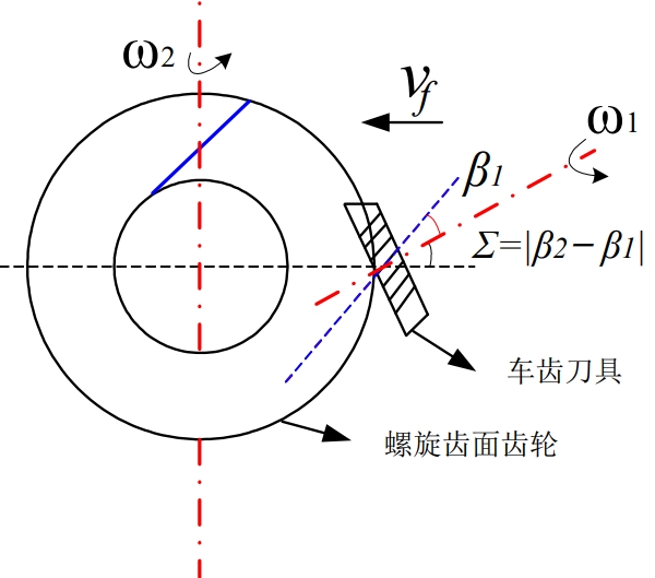
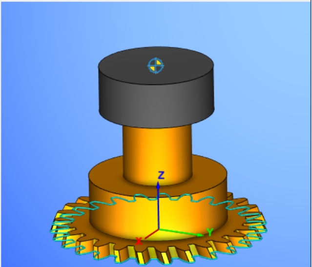
According to the spatial position relationship and the principle of tooth cutting for helical tooth gears, the motion process of tooth cutting is determinedThe parameter in , the machined face gear rotates around its own axis, and the tooth cutting tool rotates in the coordinate plane of the helical tooth surface gearThe inner rotation is a certain angle Σ, and it rotates around its axis, as shown in Figure 3.1.In addition, the tooth cutter also needs to be rotated along theThere is a feed motion in the radial direction of the face gear.
Establish the processing motion coordinate system
The kinematic diagram of gear tooth machining establishes a kinematic coordinate system for spiral tooth surface gear tooth machining, as shown in Figure 3.2.In Figure 3.2, the tooth cutter is in the coordinate system(O x y z s s s s , , , )Rotate around xs by angle Σ to reach the position for processing the gear teeth,In the coordinate system(O x y z g g g g , , , )Rotate φ1 around its zg axis according to the given parameters, and the machined face gear is in the coordinate system(O x y z m m m m , , , )Rotate φ2 around the zm axis.L represents the distance between the apex of the tool’s rake face and the center point of the face gearFirst, start to adjust the tool so that L is the same as the outer radius of the machined face gear, which is noted asL2During the processing,As the tool continues to feed radially, Lcontinuously decrease untilL.When it is equal to the inner radius of the face gear, it is recorded asL1. LOn the machineRepresented in the fixed coordinate system of the bedL2and withL1The difference value of the face gear tooth width is expressed as the tooth width of the face gear in the face gear coordinate system.To ensure the accuracy of the cutting process,To reduce the accuracy of the model, it is usually necessary to continue to feed a safety distance of 2mm after processing the entire tooth width.
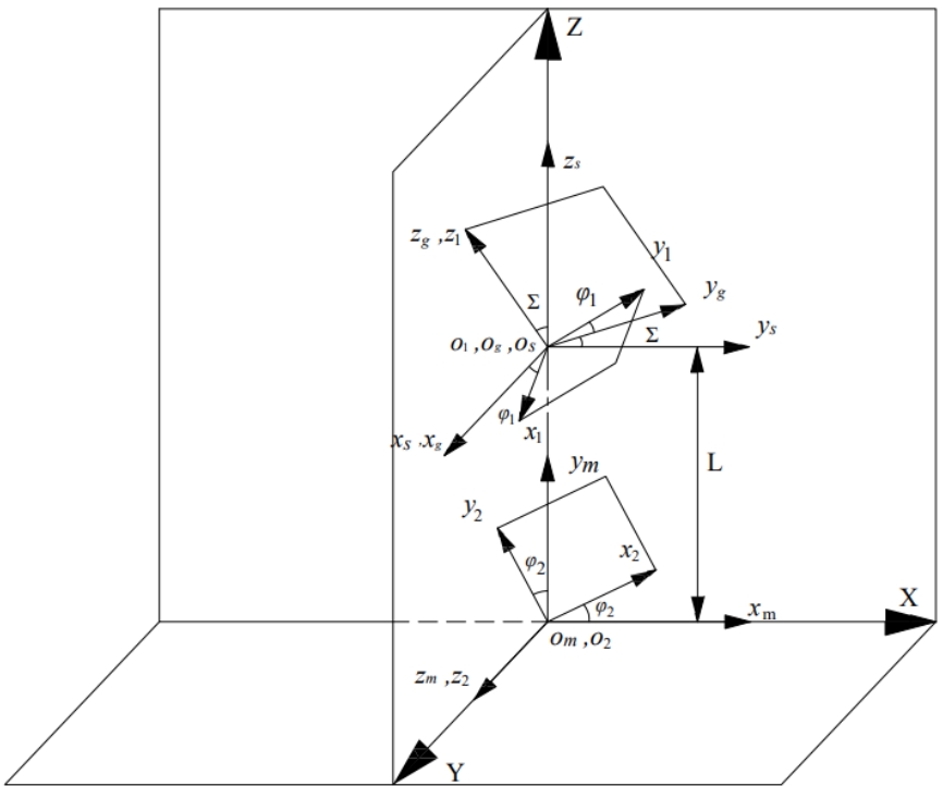
Determine the motion parameters for gear tooth machining
The motion coordinate system for gear cutting can be seen that the gear cutting machine tool needs to satisfy six degrees of freedom: threeLinear motion and three rotary motions. The three linear motions are to adjust the relative position of the face gear and the tool, and the three rotary motions are to adjust the relative position of the face gear and the tool.The motion is the rotation of the tool spindle itself, the rotation of the tool spindle in the X, Z plane of the machine tool, and the rotation of the workpiece itselfExercise.
During the process of gear tooth cutting for helical tooth gears, the radial feed rate of the gear cutting tool is taken as v=0.001mm/s, and the radial feedThe distance moved per second is 0.001mm, and it is set that the tool feeds a distance in the radial direction every time the helical tooth gear rotates one turn.The specific values of φ2 and φ1 can be determined according to the parameters of the face gear to be processed.
Design of the gear cutting tool
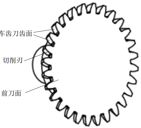
The grinding methods of the rake face of the gear cutting tool can be roughly divided into petal-shaped gear cutting tools andThe bowl-shaped gear cutting tool.The petal-shaped gear cutting tool is formed by tilting the rake angle on a plane perpendicular to the spiral line, resulting in aThe front cutting surface of the tool is designed as a conical surface, while the bowl-shaped gear cutting tool design uses the entire end surface as theThe rake face of the tool.The petal-shaped gear cutting tool has two cutting edges with similarThe wear of the cutting edge is relatively even.However, when grinding the tool, each tooth needs to be ground sequentially,Therefore, the grinding efficiency of the petal-shaped gear cutter is low, the cost of use in the later stage is high, and the accuracy is easily affected by factors such as clamping during grinding.The influence of factors.For bowl-shaped gear cutting tools, due to the conical design of the bowl-shaped gear cutting tool’s rake face, grindingWhen it comes to grinding, it is more convenient and the cost of use in the later stage is relatively low.
Structural parameter design of the tooth cutting tool with conical rake face
The establishment of the tooth-turning model for helical tooth gear
Create a 3D model of the machine tool parts in a 3D software, assemble them in the 3D model, and make each componentbetween them to form a complete machine tool model, export the components to .stl format, and import them into the VERICUT software.Open the file, add the kinematic relationship between the various components of the machine tool, set the machine tool parameters, and add tool models and blank models, respectively.Write CNC programs, debug them in software, set the motion parameters for gear machining, and design the spiral tooth surface gearSimulate the tooth processing.
Establish a machine tool model
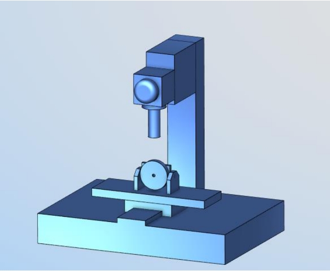
According to the kinematic relationship and coordinate system of gear cutting, a machine tool model is established in 3D software to make itThe axes cooperate with each other to meet the requirements of tooth machining movement.The machine tool model first includes three moving axes: X, Y, and Z, followed byThe spindle C axis of the tool, in addition to the rotation axis B axis of the workpiece, needs to be set.The schematic diagram of the established machine tool model is shown in Figureshow.
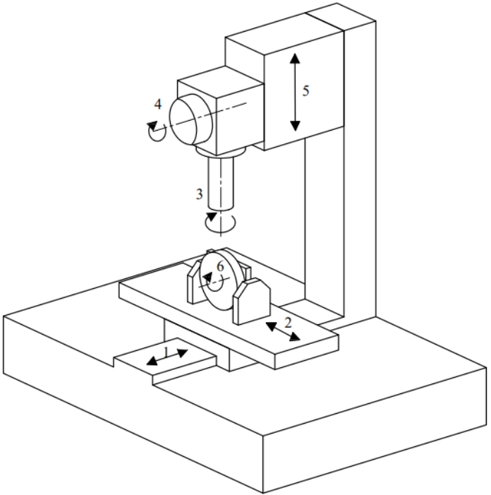
The Y-axis controls the forward and backward movement of the workbench, allowing adjustment of the distance between the machined face gear and the toolThe X axis can control the left and right movement of the workbench, allowing for the machining of offset surface gears. The Z axis canThe axis controls the up-and-down movement of the tool spindle, enabling radial feed motion of the tool.The A axis controls the tool spindle in the XZ plane.In-plane rotation, usually ranging from ±120°, with the B axis controlling the rotational motion of the machined helical tooth gear, ranging from 0-360°, the C axis is the tool spindle, which controls the rotational motion of the tool.
Model the components of the machine tool in 3D software, assemble them according to the designed motion position, and save the modelFile and assembly relationship, export each file in .stl format.In the VERICUT software, add the machine model, and add the configuration model corresponding to the configured components based on the machine project tree on the left side of the software interface to obtain the configuration model in the VERICUT software.The tooth machine tool model in is shown in the figure, and the project tree of the machine tool is shown in the figure.
The creation process of the tool model and the machine tool model is roughly similar. The tooth cutting tool model is established in the 3D software and exported.In the VERICUT project tree, select the machining tool, and in the pop-up window, select Import CAD for .stp format.The tool is loaded in the tool model created in the 3D software, and the cutting surface of the tool is selected, as shown in the figure. The tool holder is added.Select the tool setting point and the clamping point, and save the tool model, as shown in the figure.


Build a model of a spiral tooth surface gear lathe, add a prop model and a face gear blankmodel, write CNC programs, debug the motion parameters of gear machining, and start simulation processing.In the simulation software processing, you canSet the processing parameters and directly process the entire tooth height in one step, without multiple cycles of processing. In actual processing,It is necessary to consider the parameters of the machine tool and the cutting tool, and set multiple cycles of processing until the entire tooth height is processed.
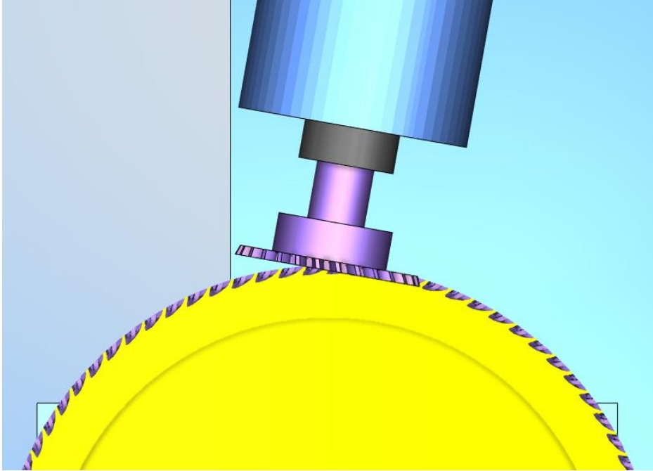


The tooth machining principle of helical tooth gears is simulated through VERICUT CNC machining simulation software.The process is simulated virtually to further verify the correctness and feasibility of spiral tooth surface gear tooth machining.According to the spiral tooth surfaceThe theory of gear tooth machining principles, analysis of tooth machining motion, and rotation of tooth cutting tools and face gears in unit timeAt one angle, the gear cutting tool simultaneously feeds a distance along the radial direction of the face gear, cutting out the entire tooth width of the face gear, completing the screwThe tooth machining process of the helical tooth surface gear.Designing the bowl-shaped tooth cutting tool structure, establishing the three-dimensional model of the tool, and mastering the cutting edge of the toolThe method of shaping the shape curve.Based on the analysis of the gear machining motion, a gear machining motion machine tool model is established in 3D software, and theImport the machine tool model into the control processing simulation software.Write the CNC processing program for machining spiral tooth surface gears, and complete the screwSimulation of tooth machining for a gear with a helical tooth surface, analysis and comparison of simulation results, and further research on CNC programming for tooth machiningThe correctness and feasibility of the spiral tooth surface gear cutting method are verified through simulation processing.
For existing tooth machine tools, establish a tooth machine tool model corresponding to their motion relationship in the simulation software.Based on the rules and general methods obtained from the simulation of machining spiral tooth surface gears by turning, the simulation of machining straight tooth surface gears by turning is carried out.True.Based on the given parameters of the tool and face gear, combined with the requirements for tool manufacturing and processing, a 3D model of the tool is created, as shown in the figureAs shown in the figure, the basic parameters of the tool are shown in the table.Add the blank model of the face gear, perform simulation processing, and straighten the teethFace gear can be considered as a special case of helical tooth surface gear.The simulation process of straight tooth surface gear is shown in Figure .

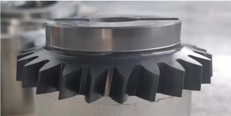
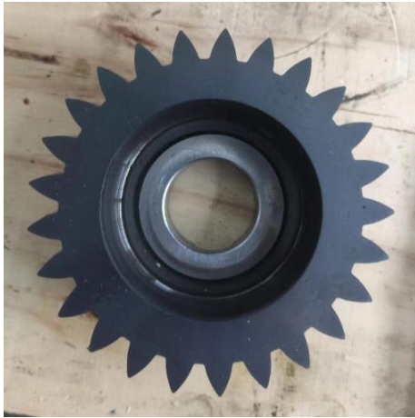
The tooth machining principle of helical tooth surface gears, combined with factors such as machining equipment, selects the tooth machining straight tooth surface gears.The spur gear is a special case of the helical gear, which is obtained based on the general simulation process of helical gear tooth machining.Regularly simulate, process, analyze, and compare the straight tooth surface gears for machining, and verify the feasibility of the tooth machining test plan.The straight tooth surface gear is processed by the tooth lathe of Luoyang Keda Yuege CNC machine tool, and the processedThe tooth surface of the spur gear is tested to further verify the correctness and feasibility of the tooth machining surface gear from a test perspective.
Helical tooth surface gear drive is a new type of spatially staggered non-parallel shaft gear drive in face gear drive. It isIt consists of an involute helical pinion gear meshing with a helical tooth surface gear.The helical tooth surface gear drive has a compact structure,Features such as high coincidence, high transmission ratio, and strong load-bearing capacity, robot joints, vehicle rear axle reducers, helicoptersThis topic takes the helical tooth surface gear with large helical angle as the research object, and proposes a method forThe tooth machining method of helical tooth surface gears is derived from the principle of spatial tooth surface meshing and the analysis of tooth machining motion, resulting in a helical toothThe tooth surface equation of the face gear is established, and a three-dimensional model is created.A bowl-shaped gear cutting tool is designed, and the simulation software VERICUT is used toThe main research results and conclusions of the paper are as follows:As shown below:
(1) Based on the gear shaving principle of helical tooth surface gears, the tooth surface equation of helical tooth surface gears is established. According to the gear shavingThe processing principle is established, and the coordinate system of gear machining surface is established. According to the principle of spatial gear meshing, the involute cylindrical tooth is established.The tooth surface equation of the wheel is derived based on the meshing relationship between involute cylindrical gears and helical tooth surface gears.Theoretical tooth surface equation.According to the numerical calculation method, the tooth surface of the helical tooth surface gear is meshed, and the three-dimensional coordinate system of the tooth surface is established.The coordinates of the punctuation and the two-dimensional projection points are used to solve the obtained tooth surface equation, and the discrete state of the helical tooth surface gear tooth surface is obtainedThe point coordinates are imported into 3D software for data processing, resulting in a 3D digital model of the helical tooth surface gear.(2) Based on the principle of spatial tooth surface meshing, a method for machining helical tooth surface gears is proposed.According to the principle of gear tooth machining,The spatial position layout of the tool and workpiece is established, and the tooth surface equation of the bowl-shaped gear cutting tool is established.According to the spatial tooth surface meshingThe principle and kinematic relationship of gear tooth machining are derived, and the equation of the helical tooth surface of gear tooth machining is derived.Based on the obtained tooth surface distanceEstablish a tooth surface error analysis model using scatter coordinates, and compare the tooth surfaces of the obtained helical tooth surface gear and the theoretical gear profileError analysis and comparison.(3) Analyze the tooth-forming motion of spiral tooth gears and simulate the tooth-forming process of spiral tooth gears.Based on the simulation results,The principle of tooth processing is analyzed by analyzing the motion of gear cutting, and the motion parameters during gear cutting are determined.The bowlThe three-dimensional model of the tool was established based on the structure of the gear tooth cutting tool, and the method of modifying the cutting edge curve of the tool was studied.According to the gear tooth machiningAnalyze the parameters of each axis of the motion, establish a three-dimensional model of the gear tooth machine tool, and import it into the VERICUT numerical control machining simulation softwareModel the gear processing machine tool, write the numerical control processing program, complete the simulation of gear processing of spiral tooth surface wheel, and analyze the simulation resultsThrough analysis and comparison, the general rules of CNC programming for gear machining are obtained.(4) According to the tooth machining principle of helical tooth gear, combined with factors such as actual machining equipment, the tooth machining surface is processedGear test.Based on the general rules obtained from the simulation process of spiral tooth surface gear tooth cutting, a straight tooth surface gear is machined for tooth cuttingSimulation processing and analysis comparison.This topic analyzes the correctness of spiral tooth surface gear tooth cutting from theoretical calculation and simulation processingand feasibility, considering factors such as on-site processing equipment, design a tooth testing plan, and utilize theThe tooth lathe machine performs tooth processing on the straight tooth surface gear, and performs tooth surface testing on the straight tooth surface gear after processing is complete.The inspection report generated by the gear measuring machine shows that the error of the left tooth surface is 74.4μm, and the error of the right tooth surface is60.7μm, through the test, the correctness and feasibility of the gear machining surface can be further verified.
The research on helical tooth gears in this article is limited by the author’s own limited abilities and experimental conditions. In order to betterThrough in-depth research on helical tooth gear transmission, the following follow-up research work is proposed:(1) The shape modification design of the bowl-shaped gear cutting tool.Due to the involute curve of the gear cutting tool designed in this paper, the simulationDuring the process, it can be clearly observed that the machining error is relatively large. Due to the limited ability of the author, only the tooth height of the tool can be modified.The design performs bidirectional modification of the tooth height and width of the tool edge curve to improve the machining accuracy of helical tooth gears.(2) Experimental research on helical tooth surface gears.Due to the influence of experimental equipment, processing requirements, and other factors, only straight tooth surfaceThe gear is processed with gear teeth, and the next step is to process the helical tooth surface gear and measure the tooth surface.(3) Explore the influencing factors of spiral tooth surface gear tooth machining.Analyze the machine tool parameters, tool parameters,The possible impact is to optimize the parameters of the spiral tooth surface gear process for machining vehicle gears.