
Helical tooth surface gear transmission is a spatial non-parallel shaft gear transmission form, which is composed of a cylindrical gear and a helical gear.It is composed of meshing gears with helical tooth surfaces.Compared with bevel gear transmission, the helical tooth surface gear transmission has a higher degree of overlap and tooth surface contact.sufficient, but also more stable, less noisy, in the areas of robot joints, vehicle rear axle reducers, helicopter reducers, etc.The existing face gear machining methods are mainly suitable for straight tooth face gears and small helix angles.The face gear cannot be formed by generating the tooth surface with a large helical angle, so this article focuses on the development of a face gear with a large helical angle.Due to the limitations of traditional machining methods, the technology of machining helical gears by gear turning method was proposed and studied. The main contents are as follows:Based on the principle of gear shaving for helical tooth gears, the tooth surface equation of helical tooth gears is constructed. According to theThe kinematic relationship of gear shaper machining is established, and a gear coordinate system for gear shaper machining is established. Based on the tooth surface equation of involute cylindrical gears,The meshing relationship between involute cylindrical gears and helical tooth surface gears is derived, and the theoretical tooth surface equation of the surface gear is derived.The discrete point coordinates of the helical tooth surface gear tooth surface are obtained by using the numerical method, and then the helical tooth surface gear is obtained by using the three-dimensional software.Three-dimensional digital model.Based on the principle of spatial gear meshing, a method for machining large helical face gears using small helical angle bevel gear cutting tools is proposedMethod.A theoretical machining model for generating helical gears with two degrees of freedom using the tooth-in-wheel method was constructed, and the spatial coordinates of the tool and workpiece were obtained.The mathematical model of the bowl-shaped tooth cutting tool edge curve is established based on the spatial layout, and the analysis of the machining motion is carried out according to the tooth cutting method.The kinematic relationship between the double-degree-of-freedom envelope principle of spatial curved surfaces and the tooth-cutting method is derived, and the helical tooth surface of the tooth-cutting method is derived.The tooth surface equation.Based on the coordinates of the discrete points on the tooth surface obtained, an error analysis model of the tooth surface is established, and the obtained spiral tooth surface error is analyzed.The tooth surface error analysis and comparison between the tooth surface and the theoretical tooth surface are carried out.A motion model for the CNC machining of helical gears using the gear cutting method was constructed, and the helical gears were CNC machinedTooth machining simulation.Based on the structural characteristics of CNC machine tools for machining helical tooth gears, a three-dimensionalBased on the kinematic transformation relationship between the theoretical model of face gear tooth cutting and the numerical control machining model, the numerical control machining of face gear tooth cutting is simulated using the model.The motion was analyzed to determine the motion parameters of each axis for the CNC machining of the gear tooth method.The structure of the bowl-shaped gear tooth cutter was designed, and theThe method of modifying the cutting edge curve of the tool is used to establish a three-dimensional model of the tool.Using the VERICUT numerical control machining simulation software,Import the machine tool and tool model, use the motion parameters of each axis of the CNC machine tool obtained from the above to write the CNC machining program, and carry outSimulation of spiral tooth surface gear machining by lathe tooth method, and analysis and comparison of simulation results, further research on CNC lathe toothGeneral rules for NC programming of spiral tooth surface gears.Based on the above-mentioned tooth-cutting method for spiral tooth gear machining, taking into account factors such as machining equipment, tooth-cutting method machining was carried out.Face gear test.According to the general method obtained from the simulation process of spiral tooth surface gear tooth processing, the straight tooth surface is processed by tooth cutting methodThe gear is simulated and analyzed for comparison.Based on the actual processing equipment parameters, a face gear tooth turning test plan is designed, which utilizesUsing the tooth-turning machine of Luoyang Keda Yuege CNC machine tool, the straight tooth surface gear was processed by tooth-turning method, and after the processing was completed,The tooth surface of the spur gear was inspected, and the inspection results showed that the error of the left tooth surface was 74.4μm, and the error of the right tooth surface wasThe correctness and feasibility of machining surface gears by the tooth method can be further verified through experiments at 60.7 μm.
Face gear transmission is a form of gear transmission in which cylindrical gears mesh with conical gears.Compared to bevel gear transmission,It has the advantages of small size, light weight, low noise, and strong load-bearing capacity.Face gear transmission has a wide range of practical applications.From low-power to high-power drives, such as rear-view mirror actuators, low-antenna drives, windshield wiper systems, fishingTools, fishing gear, robot joint reducer, automotive rear axle reducer, helicopter main reducer, etc. Compared to straight tooth surface gearWheel transmission and helical tooth gear transmission have the characteristics of compact structure, high coincidence, high transmission ratio, and strong load carrying capacity.The helical tooth surface gear transmission device consists of a helical tooth surface gear and a cylindrical gear, which are combined according to the helical tooth surface gear shaft andThe positional relationship of cylindrical gear shafts during meshing can be divided into orthogonal and non-orthogonal meshing modes. Orthogonal face gear transmissionsIt can be divided into offset surface gear transmission and concentric surface gear transmission.Generally, the manufacturing methods of gears are divided into hobbing and gear shaving.Gear shaving is a process of making involute pinion gears into gears by insertingThe tooth cutter is used to process face gears through generating motion, usually used to process straight-tooth face gears due to the existence of idle motion during the processing process.and discontinuous phenomena, resulting in low processing efficiency;hobbing is the use of worm hob instead of gear shaper for processing, but hobbingGenerally, only straight tooth surface gears and helical tooth surface gears with relatively small helical angles can be processed, and the resulting helical surface is not as accurate as the theoretical tooth surface.There is a large deviation in the shape surface.Due to the complex tooth profile of the helical tooth surface gear, it is necessary to adopt hobbing or gear shaving processing when processing.Using dedicated machine tools and cutting tools, the development process of cutting tools is generally cumbersome, making them unsuitable for practical production.If traditional additive manufacturing methods are used,CNC milling is used for machining, which avoids the development of proprietary tools, but due to theWhen machining a face gear with a large helical angle using the milling method, its machining accuracy is greatly affected, resulting in low machining efficiency and increased machining difficulty.The high cost of labor cannot meet the high-efficiency and precise processing technology requirements required for face gear transmission in the high-speed and heavy-duty fields.The gear tooth method is a cutting method combining hobbing and gear shaving. During the cutting process, the workpiece and tool are connectedContinuous rotation.With the continuous in-depth research of CNC machine tools and cutting tools, the tooth processing technology has gradually matured.The tooth processingThe technology is applied to spiral tooth gears, and through tool design and workpiece layout design, the tooth cutting process of spiral tooth gears can be obtained.The method can greatly improve the processing efficiency and quality of face gears, which is of great significance for the practical processing of helical tooth gears.The production has important engineering application value.
Face gear transmission is usually used to transmit motion between intersecting or staggered axes in space. The face gear transmission device consists of a face gear,It is composed of spur gears or helical gears, with a shaft angle of typically 90°, but can also be designed with other shaft angles, face gear module, pressure angleis a variable value, but can achieve a constant transmission ratio.Face gear transmission is usually used in helicopter transmission, where theWheel drive provides the possibility of distributing torque between two face gear drives, which can be successfully applied to reduce weight and cost.This advantage has aroused people’s new interest in face gear transmission. If conditions permit, face gear transmission can replacereplaced with bevel gear and hypoid gear.
Helical gear drive is composed of cylindrical gears and face gears with variable helical angles, pressure angles, and moduleWhen the axial angle between the cylindrical gear and the face gear is 90°, this form of transmission is called orthogonal face gear transmission.On the contrary, it is called non-orthogonal face gear transmission.Orthogonal face gear transmission can be divided into centering face gear transmission and offset face gear transmission.Gear transmission.Figure is a schematic diagram of orthogonal transmission of helical tooth gears, where Figure shows offset surface teethThe layout diagram of the wheel transmission device shows the layout diagram of the orthogonal centering surface gear transmission device.
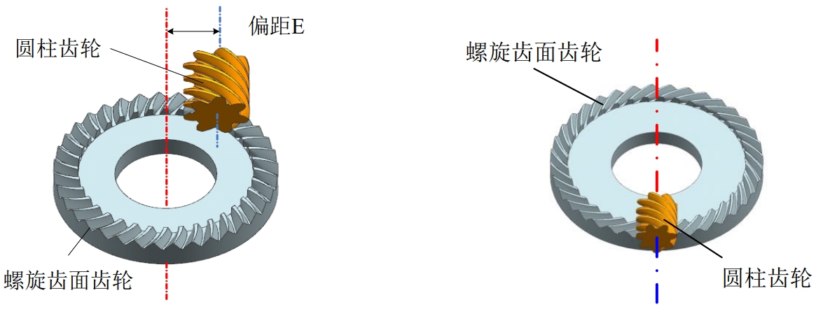
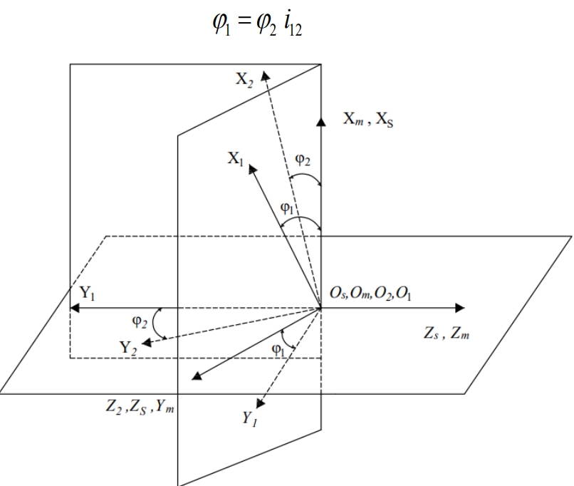
The orthogonal transmission of helical tooth gears has the following advantages:(1) In non-orthogonal face gear transmission, the gear meshing with the face gear is a conical gear;in orthogonal face gear transmission, the gear meshing with the face gear is a cylindrical gear.The face gear meshes with an involute cylindrical gear, and the axial offset error of the cylindrical gear almost does not affect the performance of the transmission device.(2) Spiral tooth surface gears are in linear contact with cylindrical gears, which is more efficient than non-orthogonal bevel gear transmissions.The transmission efficiency of gears is higher.Compared to non-orthogonal bevel gear transmission, orthogonal face gear transmission has a higher degree of coincidence,The lower coincidence degree can reach 1.6-1.8, and the high coincidence degree gear transmission structure will improve the stability of the entire transmission system.The main research object of this topic is the orthogonal face gear transmission. For ease of description, the orthogonal face gear transmission mentioned in the textDynamic gear transmission refers to the transmission of power between the meshing gears.This chapter takes the example of the meshing of left-hand involute cylindrical gears and helical tooth gears, based on the principle of helical gear transmission.The principle of gear shaving for tooth-face gears, establishment of the shaving coordinate system, establishment of the tooth-face equation for cylindrical gears, and the calculation of tooth-face contact points based on the spatial gear meshThe theoretical tooth surface equation of the helical tooth surface gear is derived based on the principle of symmetry, and the tooth surface equation is solved using numerical calculation methods.Theoretical tooth surface discrete point coordinates of the spiral tooth surface gear are obtained, and three-dimensional modeling is performed using three-dimensional software.Based on the tooth profile of the face gearProcessing principle, establishing tooth surface equation of gear cutting tool, designing spatial position layout relationship between tool and workpiece;based on spatial gearDerive the surface gear tooth surface equation for gear tooth machining based on the meshing principle and the kinematic relationship between gear tooth machining.Establish a tooth surface error analysisThe model is used to analyze the errors between the obtained tooth surface and the theoretical tooth surface, and to perform 3D digital modeling.
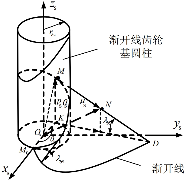
Involute cylindrical gears are composed of straight involute tooth profiles and spiral lines on the base cylinder.M M0Tangent straight line around cylindrical toothThe rotation center of the wheel forms a spiral motion.
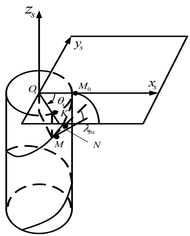
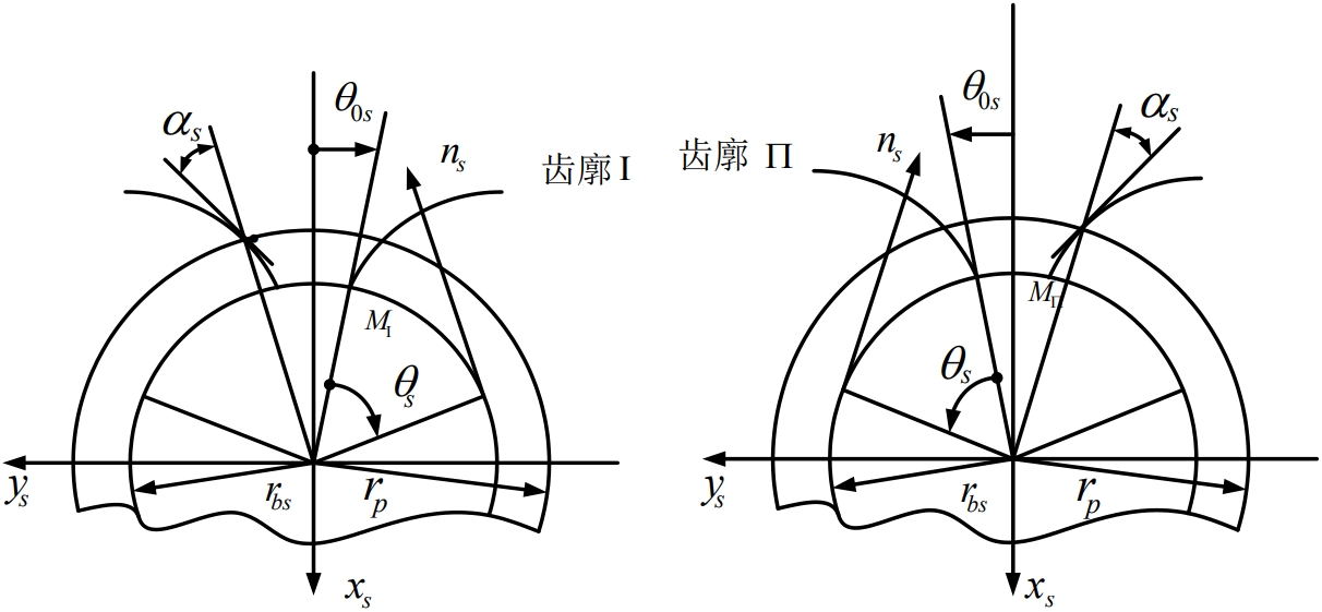
According to the principle of gear machining, when the tool and the workpiece are in external gear meshing, the positive sign applies to the workpiece and the tool helical line squareIn the same situation, the negative sign applies to the case where the workpiece and the tool have opposite helical directions;when the tool and the workpiece are in internal gear mesh, the negative sign is not applicable.When appropriate, the positive sign applies to the case where the workpiece and tool spiral directions are opposite, and the negative sign applies to the case where the workpiece and tool spiral directions are the same.The same situation.Such a layout can ensure the conjugate normal profiles of the workpiece and the tool, and through the rational design of the normal profile of the tool,The tooth profile can ensure the accuracy of tooth shape processing.
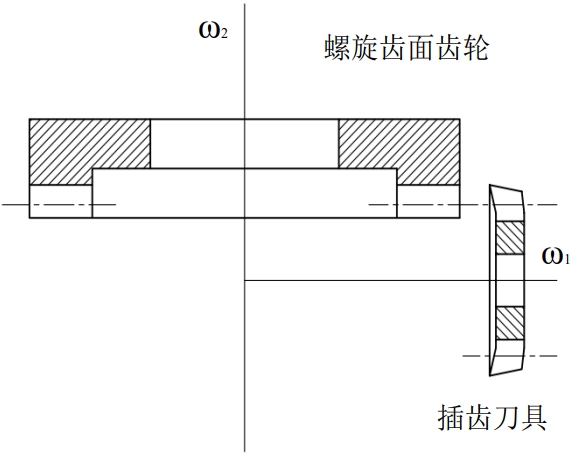
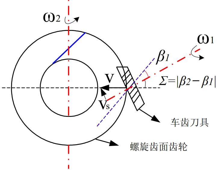
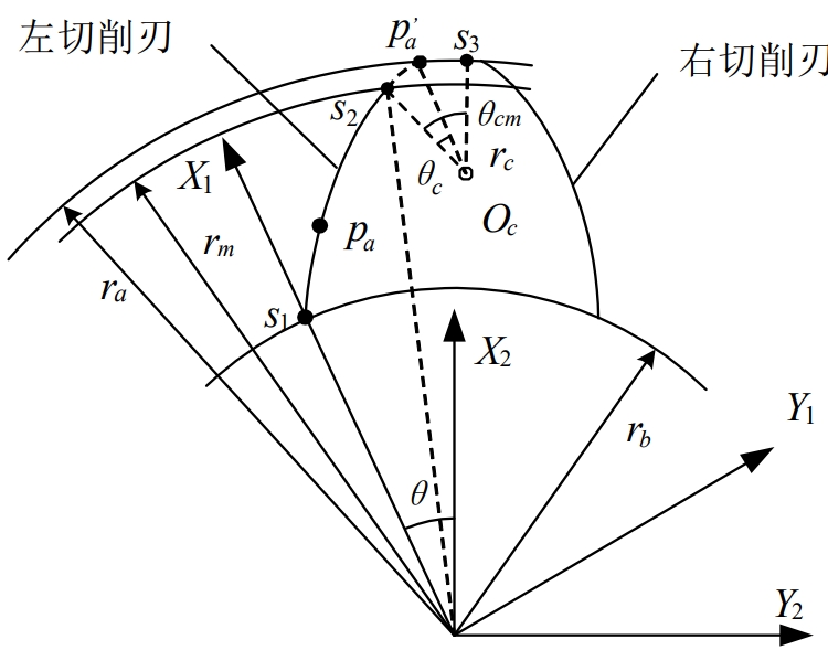
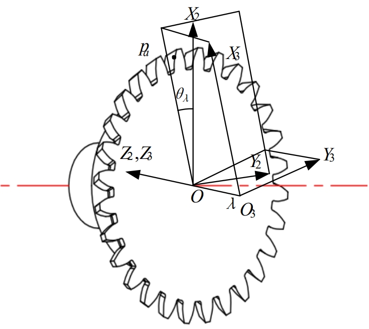
The tooth machining process uses a fixed rolling ratio between the tool and the workpiece to generate a relative cutting speed for cutting.The tooth machining of a helical tooth surface gear requires the following motions: the tooth cutting tool rotates around the axis 𝑧 1 at an angular velocity𝜔1, and the helical tooth surfaceThe gear rotates around the axis𝑧2 at an angular velocity 𝜔 2. In order to machine the entire tooth width, the gear cutting tool needs to move along the helical tooth surface at a speedᓯ𝑓.The radial feed motion in the radial direction breaks the original meshing relationship between the gear cutting tool and the machined helical gear surface. At this point, an additional rotation angle can be added to the original rotation of the tool or workpiece to ensure the accuracy of the machining process.The correctness of the tooth profile is related to the additional rotation angle and the feed rate of the workpiece along the axis.
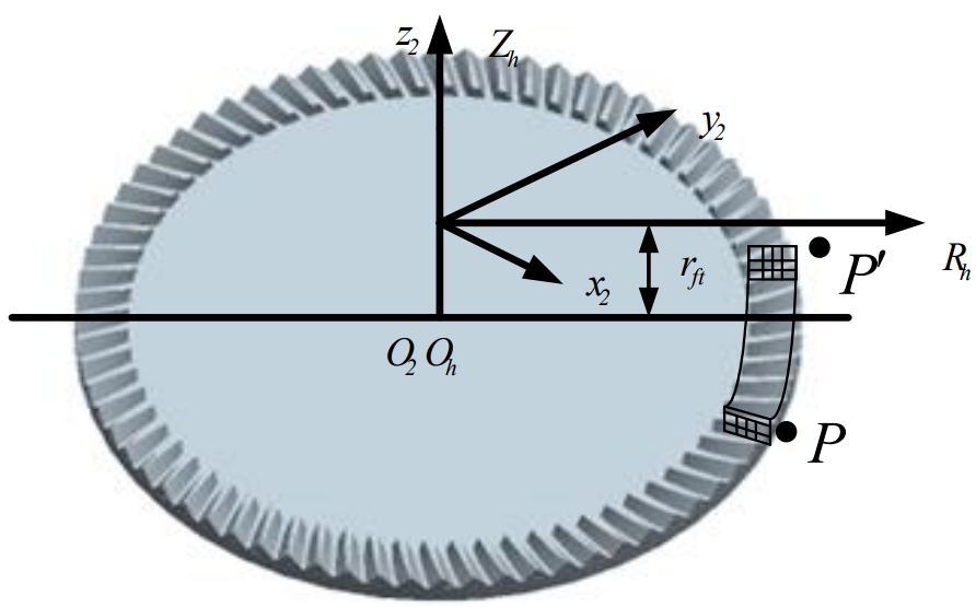
During the process of gear tooth machining, due to the need to ensure that the formation of the workpiece tooth surface is completely dependent on the cutting edge of the gear tooth cutting tool, it is necessary toWhen grinding, the side of the tool itself has no effect on the profile of the tooth surface.The rake angle of the cutting edge is determined by the angle between the rake face and the flank of the tooth.The space curve formed by intersection, while the gear cutting tool itself can be approximated as a helical cylindrical gear, which can be cut by a helical cylindricalAdding the rake angle and clearance angle of the tool on the gear will result in the structure of the tooth cutting tool.
The tooth surface of a helical tooth surface gear consists of a working tooth surface and a tooth root transition surface.The working tooth surface is formed by the tooth surface of the cutting toolThe transition tooth surface is formed by sweeping the tooth tip line of the gear cutting tool.A curved surface is formed during the rotation of the tool tooth surface.For each cluster, there is a contact curve between each surface and the tooth surface of the face gear. This contact curve can be obtained from the gear meshing principle, andNumerous such curves form the tooth surface of the face gear.