
I designed a single acting rack and pinion hydraulic actuator for valve remote control systems in marine ventilation service. The core motion conversion is performed by rack and pinion gears: the linear travel of a rack drives a pinion shaft through a controlled rotation, and the pinion shaft operates the valve. When the hydraulic power source is lost, a disc spring stack releases stored elastic energy, pushes the rack in the opposite direction, and closes the valve automatically. This fail-safe behavior is the main reason I selected a single acting configuration. The design offers a simple mechanical arrangement, a small installed height, high output torque, straightforward installation, and relatively low manufacturing cost. I established mathematical models for the rack and pinion gears, the disc spring stack, the cylinder wall thickness, and the working volume. I then created a three-dimensional virtual prototype, manufactured a physical sample, and tested torque, pressure, and leakage. The measured data confirmed that my mathematical models and parameter selections were accurate enough for engineering development.
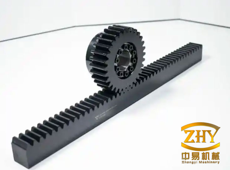
1. Working Principle and Structural Arrangement
In my design, the actuator body contains a cross-shaped internal cavity. The rack moves linearly inside one branch of the cavity, and the pinion shaft rotates inside the intersecting branch. The rack and pinion gears mesh directly, so every millimetre of rack travel produces a proportional angular rotation of the pinion. A hydraulic piston is connected to the rack. Hydraulic oil enters chamber A and pushes the piston, which moves the rack and rotates the pinion. At the same time, the piston compresses a disc spring stack in chamber B. When the valve reaches the fully open position, a position indicator triggers a switch and stops the pump motor. If the power source is lost, a two-way two-position solenoid valve returns to its normally open position, the hydraulic oil in chamber A is discharged to the reservoir, and the compressed disc spring stack pushes the rack back. The rack and pinion gears then rotate the pinion in the closing direction, and the valve closes automatically.
The main structural groups are the body, rack, pinion shaft, cylinder barrels, end caps, single acting pistons, disc springs, guide rods, limit bolts, seals, and port fittings. The rack and pinion gears are lubricated by the hydraulic oil environment and are protected from external contamination. The limit bolts define the fully open and fully closed positions. The guide rods keep the disc spring stack aligned and prevent lateral buckling. The piston carries wear rings, U-cups, and glyd rings to seal the hydraulic chamber and to reduce friction. The spring chamber is vented so that the disc springs can move freely without trapping air pressure.
| Subsystem | Function | Design Consideration |
|---|---|---|
| Body | Houses rack and pinion gears and forms the cross cavity | High stiffness, accurate bore alignment, corrosion resistance |
| Rack | Converts hydraulic linear force into linear motion | Bending strength, tooth wear resistance, straightness |
| Pinion shaft | Converts rack translation into rotary motion | Torsional strength, tooth root strength, bearing support |
| Cylinder barrel | Forms the pressure chamber for the piston | Wall thickness, thread strength, fatigue resistance |
| Piston | Separates hydraulic oil from spring chamber | Sealing, low friction, wear resistance |
| Disc spring stack | Stores energy for fail-safe closing | Load-deflection curve, stack length, fatigue life |
| Guide rod | Aligns disc springs and prevents buckling | Straightness, surface finish, strength |
| Limit bolt | Sets fully open and fully closed positions | Adjustment range, locking, impact resistance |
For a single acting rack and pinion hydraulic actuator, the relationship among hydraulic pressure, rack force, and pinion torque is direct. I used this relationship as the starting point for all subsequent calculations. The rack and pinion gears are the most important mechanical pair because they determine the torque capacity, the stroke, the module, the tooth count, and the installation envelope. In my model, the pinion pitch radius is the lever arm that converts rack force into output torque.
$$T = F \cdot r = F \cdot \frac{m Z}{2}$$
Here, T is the output torque, F is the tangential force at the pitch circle, r is the pitch radius, m is the module, and Z is the number of pinion teeth. For 90 degrees of pinion rotation, the rack stroke is:
$$S = \frac{\pi m Z}{4}$$
The hydraulic volume required for one full stroke is:
$$V = A S = \frac{\pi D^2}{4} S$$
where D is the cylinder bore diameter. These equations show why rack and pinion gears are well suited to compact quarter-turn valve actuation. The pinion radius directly multiplies the rack force, while the module and tooth count determine both the radius and the stroke. A larger module increases torque capacity but also increases size and weight. A larger tooth count increases the pitch radius for a given module and therefore increases torque, but it also increases the rack stroke for a given rotation angle.
2. Design Requirements and Initial Torque
I began with a required initial output torque of 160 N·m at the 0-degree closed position. The actuator must rotate through 90 degrees to reach the fully open position. The maximum hydraulic supply pressure is 13 MPa, and the test pressure is 19.5 MPa. The cylinder bore is 50 mm. The actuator must close automatically when the hydraulic power source is lost. The operating environment is a marine ventilation system, so corrosion resistance, reliability, and maintenance access are important. I also required a compact height because the actuator is mounted along the pipe direction in a space-limited duct system.
| Design Parameter | Symbol | Value | Unit |
|---|---|---|---|
| Initial output torque at 0° | T1 | 160 | N·m |
| Rotation angle | θ | 90 | degree |
| Maximum hydraulic pressure | p | 13 | MPa |
| Test pressure | ptest | 19.5 | MPa |
| Cylinder bore | D | 50 | mm |
| Fail-safe action | — | Spring close | — |
| Mounting orientation | — | Along pipe | — |
| Operating medium | — | Hydraulic oil | — |
For the initial torque condition, I assumed that the hydraulic pressure is not yet acting and that the disc spring stack provides the closing torque. The torque is generated by the rack force acting on the pinion pitch radius. I selected a trial module m = 3 mm and a trial pinion tooth count Z = 18. The pitch radius is therefore:
$$R = \frac{m Z}{2} = \frac{3 \cdot 18}{2} = 27 \text{ mm}$$
The initial rack force required to produce 160 N·m is:
$$F_1 = \frac{T_1}{R} = \frac{160}{0.027} = 5926 \text{ N}$$
This force is the starting point for the disc spring selection. At the 0-degree position, the disc spring stack is not fully compressed, so it must provide at least 5926 N at the corresponding deflection. As the actuator opens, the spring compression increases, and the spring force rises. The maximum spring force must not exceed the hydraulic force available at the maximum pressure. Otherwise, the actuator cannot reach the fully open position.
The rack stroke for 90 degrees of pinion rotation is:
$$S = \frac{\pi m Z}{4} = \frac{\pi \cdot 3 \cdot 18}{4} = 42.39 \text{ mm}$$
This stroke is the linear travel of the rack and the linear compression of the disc spring stack. It also determines the working volume of the hydraulic cylinder. In my design, the rack and pinion gears must be wide enough to transmit the tooth load without excessive bending stress, but not so wide that the body becomes unnecessarily large. I used a face width of 30 mm for the initial design and verified the tooth root bending strength later.
3. Rack and Pinion Gear Geometry and Strength
I treated the rack and pinion gears as the primary load-carrying mechanical pair. The pinion is the weaker member because it has fewer teeth and a smaller root width than the rack. I selected 45 steel for the pinion and applied a QPQ salt bath treatment to increase surface hardness and wear resistance. I selected 40Cr for the rack and used quenching and tempering to improve its toughness and wear resistance. The gear teeth are lubricated by hydraulic oil, so the design is protected from dry wear, but the tooth root must still resist bending fatigue.
| Material Property | Pinion: 45 Steel | Rack: 40Cr |
|---|---|---|
| Tensile strength σb | 650 MPa | 700 MPa |
| Yield strength σs | 360 MPa | 500 MPa |
| Heat treatment | QPQ salt bath | Quenched and tempered |
| Primary purpose | Surface hardness and wear resistance | Toughness and wear resistance |
I used the tooth root bending strength formula to choose the module:
$$m \ge \sqrt[3]{\frac{2 K T’}{\phi_d Z_1^2}\left(\frac{Y_{Fa}Y_{Sa}}{[\sigma_F]}\right)} = 2.97 \text{ mm}$$
In this equation, K is the load factor, T′ is the design torque, φd is the face width coefficient, Z1 is the number of pinion teeth, YFa is the tooth form factor, YSa is the stress correction factor, and [σF] is the allowable bending stress. The calculation gave a minimum module of 2.97 mm. I selected a standard module of 3 mm because it provides a small margin and simplifies manufacturing. The final pinion tooth count is 18. The resulting pitch diameter is 54 mm, and the pitch radius is 27 mm.
| Gear Parameter | Symbol | Value | Unit |
|---|---|---|---|
| Module | m | 3 | mm |
| Pinion tooth count | Z | 18 | — |
| Pressure angle | α | 20 | degree |
| Pitch diameter | d | 54 | mm |
| Pitch radius | R | 27 | mm |
| Face width | b | 30 | mm |
| Addendum | ha | 3 | mm |
| Dedendum | hf | 3.75 | mm |
| Whole depth | h | 6.75 | mm |
| Rack stroke for 90° | S | 42.39 | mm |
I also checked the tangential force at the pitch circle. For the initial torque of 160 N·m and a pitch diameter of 54 mm, the tangential force is:
$$F_t = \frac{2 T}{d} = \frac{2 \cdot 160}{0.054} = 5926 \text{ N}$$
This is the same force calculated from the pitch radius, which confirms the consistency of the rack and pinion gear geometry. The bending stress in the pinion tooth can be estimated as:
$$\sigma_F = \frac{2 T K}{b m^2 Z} Y_{Fa} Y_{Sa} \le [\sigma_F]$$
For my chosen geometry, the calculated bending stress is below the allowable value for 45 steel after QPQ treatment. The rack tooth stress is lower because the rack has more effective teeth in contact and a larger root area. The rack and pinion gears therefore satisfy the strength requirement with a module of 3 mm and a face width of 30 mm.
The rack and pinion gears also determine the lost motion and backlash. I specified a small backlash to ensure smooth rotation without binding. Because the actuator is a quarter-turn device, the pinion rotates through 90 degrees, and the rack travels 42.39 mm. The gear mesh must remain aligned over this travel. The body bore and the rack guide therefore require accurate machining. In my virtual prototype, I checked the contact pattern and confirmed that the rack and pinion gears do not interfere at either limit.
4. Disc Spring Selection and Stack Design
The disc spring stack is the energy storage element that enables fail-safe closing. I selected a disc spring type with an outer diameter of 60 mm, an inner diameter of 20.5 mm, a thickness of 3 mm, a free height of 5.2 mm, and a cone height of 2.2 mm. The ratio h0/t is 0.733. This disc spring has a nonlinear load-deflection curve, which is useful because the force increases gradually as the spring compresses. The stack is arranged in an opposed series so that the deflections add while the force remains the same as that of a single disc spring. This arrangement allows a long total stroke without increasing the force beyond the hydraulic limit.
| Disc Spring Parameter | Symbol | Value | Unit |
|---|---|---|---|
| Outer diameter | De | 60 | mm |
| Inner diameter | di | 20.5 | mm |
| Thickness | t | 3 | mm |
| Free height | H0 | 5.2 | mm |
| Cone height | h0 | 2.2 | mm |
| Ratio h0/t | h0/t | 0.733 | — |
| Stack arrangement | — | Opposed series | — |
At the 0-degree position, the disc spring stack must produce at least 5926 N to generate 160 N·m. As the actuator rotates to 90 degrees, the rack compresses the spring stack by 42.39 mm. The maximum hydraulic torque available at 13 MPa is:
$$T’_2 = p \frac{\pi D^2}{4} \frac{m Z}{2} \eta = 586 \text{ N·m}$$
where η is the mechanical efficiency. I used η = 0.85 to account for friction in the seals, guide rods, and rack and pinion gears. The corresponding maximum hydraulic rack force is:
$$F_2 = \frac{T’_2}{R} = \frac{586}{0.027} = 21703 \text{ N}$$
Therefore, the disc spring force at maximum compression must be less than 21703 N. Otherwise, the hydraulic pressure cannot fully compress the spring and the actuator will not reach the fully open position. I used the standard disc spring load-deflection equation to evaluate the force:
$$F = \frac{4E}{1-\mu^2} \frac{t^3 s}{K_1 D_e^2} \left[ \left(\frac{h_0}{t} – \frac{s}{t}\right)\left(\frac{h_0}{t} – \frac{s}{2t}\right) + 1 \right]$$
Here, E is the elastic modulus, μ is Poisson’s ratio, s is the deflection, and K1 is a geometry factor based on the diameter ratio. The calculation showed that the selected disc spring produces about 12982 N at the maximum deflection. This is well below the hydraulic limit of 21703 N. I determined the number of discs from the total stroke:
$$N_d = \frac{S}{s_{per}} = \frac{42.39}{0.785} \approx 54$$
Each disc contributes about 0.785 mm of deflection in the opposed series stack. The total spring force at maximum compression is approximately 12892 N, which is close to the single-disc value because the series stack shares the same force. The spring torque at maximum compression is:
$$T_3 = F’_2 R = 12892 \cdot 0.027 = 348 \text{ N·m}$$
The net output torque at the fully open position is the hydraulic torque minus the spring torque:
$$T_2 = T’_2 – T_3 = 586 – 348 = 238 \text{ N·m}$$
This value is higher than the initial torque of 160 N·m, so the actuator has sufficient torque margin at the fully open position. The disc spring stack also provides a predictable closing force when the hydraulic pressure is lost. I verified that the spring force at the 0-degree position is high enough to close the valve against the expected friction and flow forces. The opposed series arrangement gives a compact stack length while keeping the maximum force within the hydraulic capability.
| Spring Stack Quantity | Symbol | Value | Unit |
|---|---|---|---|
| Required initial force | F1 | 5926 | N |
| Maximum hydraulic force at 13 MPa | F2 | 21703 | N |
| Single disc force at maximum deflection | Fdisc | 12982 | N |
| Actual stack force at maximum deflection | F′2 | 12892 | N |
| Number of discs | Nd | 54 | — |
| Spring torque at maximum compression | T3 | 348 | N·m |
| Net torque at fully open | T2 | 238 | N·m |
5. Cylinder Wall Thickness and Pressure Containment
The hydraulic cylinder barrel contains pressurized oil and must resist both static pressure and test pressure. I selected 45 steel for the cylinder barrel. The tensile strength is 600 MPa. I used a safety factor of 5, which gives an allowable stress of:
$$\sigma_p = \frac{\sigma_b}{n} = \frac{600}{5} = 120 \text{ MPa}$$
The wall thickness is calculated as:
$$\delta = \delta_0 + C_1 + C_2$$
where δ0 is the minimum thickness required by strength, C1 is the outer diameter tolerance, and C2 is the corrosion allowance. For a thick-walled cylinder under internal pressure, I used the following design formula:
$$\delta_0 \ge \frac{p_{max} D}{2.3 \sigma_p – 3 p_{max}}$$
With a maximum pressure of 20 MPa, an inner diameter of 50 mm, and an allowable stress of 120 MPa, the minimum thickness is:
$$\delta_0 \ge \frac{20 \cdot 50}{2.3 \cdot 120 – 3 \cdot 20} = \frac{1000}{216} = 4.63 \text{ mm}$$
I added tolerances and corrosion allowance, and selected a final wall thickness of 5 mm. The cylinder outer diameter is therefore 60 mm. I also checked plastic deformation. The allowable pressure for plastic deformation is:
$$p_N \le 0.35 \sigma_s \frac{D_1^2 – D^2}{D_1^2}$$
With a yield strength of 355 MPa, an outer diameter of 60 mm, and an inner diameter of 50 mm, the allowable pressure is:
$$p_N \le 0.35 \cdot 355 \cdot \frac{60^2 – 50^2}{60^2} = 37.97 \text{ MPa}$$
I also used the empirical relationship:
$$p_N \le (0.35 \sim 0.42) p_{rL}$$
This check ensures that the barrel does not experience fully plastic deformation at the test pressure. The bottom thickness of the cylinder is calculated as:
$$\delta_1 \ge 0.433 D_2 \sqrt{\frac{p}{\sigma_p}}$$
Using an effective diameter of 50 mm, a maximum pressure of 20 MPa, and an allowable stress of 120 MPa, the minimum bottom thickness is:
$$\delta_1 \ge 0.433 \cdot 50 \sqrt{\frac{20}{120}} = 8.84 \text{ mm}$$
I selected a bottom thickness of 9 mm. These calculations show that the cylinder barrel and end caps can withstand the maximum working pressure and the required test pressure without permanent deformation or leakage. The threaded connection between the barrel and the body also requires sufficient engagement length. I verified the thread shear area and ensured that the thread length is at least 1.5 times the nominal diameter.
| Pressure Containment Check | Symbol | Value | Unit |
|---|---|---|---|
| Ultimate tensile strength | σb | 600 | MPa |
| Safety factor | n | 5 | — |
| Allowable stress | σp | 120 | MPa |
| Maximum pressure | pmax | 20 | MPa |
| Inner diameter | D | 50 | mm |
| Minimum wall thickness | δ0 | 4.63 | mm |
| Selected wall thickness | δ | 5 | mm |
| Outer diameter | D1 | 60 | mm |
| Plastic deformation limit | pN | 37.97 | MPa |
| Minimum bottom thickness | δ1 | 8.84 | mm |
6. Working Volume and Flow Demand
The working volume of the single acting hydraulic actuator is the volume swept by the piston during one full stroke. This volume determines the pump flow required for a given actuation time. The rack stroke is 42.39 mm. The cylinder bore is 50 mm. The piston area is:
$$A = \frac{\pi D^2}{4} = \frac{\pi \cdot 50^2}{4} = 1963.5 \text{ mm}^2$$
The swept volume is:
$$V_1 = A S = 1963.5 \cdot 42.39 = 83200 \text{ mm}^3 = 83 \text{ mL}$$
If the rack diameter reduces the effective area, the effective volume is slightly lower, but for the main hydraulic supply calculation I used 83 mL. This volume is small enough that a compact pump station can open the actuator quickly. For example, if the desired opening time is 5 seconds, the required flow is:
$$Q = \frac{V_1}{t} = \frac{83}{5} = 16.6 \text{ mL/s} = 1.0 \text{ L/min}$$
This flow rate is low, which helps keep the pump and motor small. The single acting design also means that the return stroke is driven by the disc spring stack, not by hydraulic pressure. Therefore, the hydraulic system only needs to supply oil in one direction. A two-way two-position solenoid valve can release the chamber to the reservoir when the power is lost. The working volume and the rack and pinion gears together define the actuator response time and the required reservoir size.
| Volume Parameter | Symbol | Value | Unit |
|---|---|---|---|
| Rack stroke | S | 42.39 | mm |
| Piston area | A | 1963.5 | mm² |
| Swept volume | V1 | 83 | mL |
| Example opening time | t | 5 | s |
| Required flow | Q | 1.0 | L/min |
| Return stroke energy source | — | Disc spring stack | — |
The working volume calculation also confirms the rack stroke. Because the rack and pinion gears rotate exactly 90 degrees, the stroke cannot be arbitrarily changed without changing the pinion pitch radius or the tooth count. I kept the module at 3 mm and the tooth count at 18 to maintain the required torque and stroke. The volume gives me a direct check on the hydraulic power unit: the pump must deliver at least 83 mL per opening stroke, plus a small allowance for leakage and oil compressibility.
7. Virtual Prototype and Manufacturing
After completing the mathematical models, I built a three-dimensional virtual prototype of the single acting rack and pinion hydraulic actuator. The model included the body, rack, pinion shaft, cylinder barrel, end caps, piston, disc springs, guide rods, limit bolts, and all seals. I used the virtual prototype to check interference, alignment, and assembly sequence. I simulated the motion of the rack and pinion gears through the full 90-degree rotation and confirmed that the rack travels 42.39 mm without binding. I also checked the clearances around the disc spring stack and verified that the stack can compress to its maximum deflection without coil clash or guide rod contact.
The virtual prototype helped me refine several details. The guide rod diameter must be small enough to fit inside the disc spring inner diameter but large enough to resist buckling. The piston seal grooves must be positioned so that the seals do not roll or extrude under pressure. The limit bolts must be accessible after assembly so that the open and closed positions can be adjusted. The pinion shaft bearings must support the radial load from the rack and the torque load from the valve. I also checked the wall thickness of the body at the cross cavity, because the rack and pinion gears create a complex stress distribution.
For manufacturing, I selected standard machining processes. The body is machined from a cast or forged blank. The rack and pinion gears are cut with standard gear hobbing or shaping tools. The pinion receives QPQ treatment after machining. The rack is quenched and tempered before tooth cutting. The cylinder barrel is honed to achieve the required surface finish and roundness. The piston is turned and grooved for seals. The disc springs are purchased as standard components and stacked in the opposed series arrangement. The end caps and limit bolts are machined from steel and plated for corrosion protection. After assembly, the actuator is filled with hydraulic oil and tested for leakage and torque.
| Manufacturing Step | Process | Quality Check |
|---|---|---|
| Body machining | Milling, boring, drilling | Bore alignment, cross cavity position |
| Rack machining | Turning, gear cutting, heat treatment | Tooth profile, straightness, hardness |
| Pinion machining | Turning, gear cutting, QPQ treatment | Tooth profile, surface hardness, runout |
| Cylinder barrel | Turning, honing, threading | Inner diameter, roundness, surface finish |
| Piston | Turning, seal groove machining | Groove dimensions, surface finish |
| Disc spring stack | Stacking, pre-compression | Free length, force-deflection curve |
| Assembly | Seal installation, torque tightening | Leakage, smooth rotation, limit positions |
The rack and pinion gears are the most critical manufactured pair. I specified a tooth profile tolerance that ensures proper backlash and contact. The pinion shaft must rotate freely in its bearings while maintaining minimal axial play. The rack must slide smoothly in its guide bore without tilting. In my sample, I used a slight preload on the pinion bearings to eliminate axial movement and to keep the gear mesh stable. I also applied a small amount of grease to the rack and pinion gears during assembly to ensure smooth operation before hydraulic oil reaches the mesh.
8. Experimental Validation
I connected the manufactured actuator to a hydraulic pump station and a torque test bench. The test bench measured the output torque at the pinion shaft while the pressure was varied. At the 0-degree position, the measured torque was close to the theoretical value of 160 N·m. At the fully open position with 13 MPa supply pressure, the measured net torque was slightly lower than the theoretical value because of friction in the seals, guide rods, and rack and pinion gears. The deviation was acceptable for the design stage. The tests confirmed that the disc spring stack provides enough force to close the valve when the hydraulic pressure is released.
| Test Condition | Theoretical Torque (N·m) | Measured Torque (N·m) | Deviation (%) |
|---|---|---|---|
| 0° initial position, spring only | 160 | 158 | -1.25 |
| Fully open, 13 MPa | 238 | 226 | -5.04 |
| Spring compression torque | 348 | 335 | -3.74 |
I also tested the output torque at different supply pressures. The actuator was held at the fully open position, and the pressure was set by the relief valve. The measured torque followed the theoretical trend closely. The slight negative deviation increased at lower pressures because the friction forces became a larger fraction of the net torque. The results show that the mathematical model of the rack and pinion gears and the disc spring stack is reliable for design purposes.
| Supply Pressure (MPa) | Hydraulic Torque (N·m) | Spring Torque (N·m) | Net Theoretical (N·m) | Measured Net (N·m) | Deviation (%) |
|---|---|---|---|---|---|
| 8 | 360.6 | 348 | 12.6 | 10.5 | -16.7 |
| 10 | 450.8 | 348 | 102.8 | 96.2 | -6.4 |
| 12 | 540.9 | 348 | 192.9 | 184.5 | -4.4 |
| 13 | 586.0 | 348 | 238.0 | 226.0 | -5.0 |
For the pressure and leakage test, I set the relief valve to 19.5 MPa and held the pressure for 5 minutes. The actuator showed no permanent deformation, no external leakage, and no sudden pressure drop. The seals remained intact, and the rack and pinion gears continued to rotate smoothly after the test. I also cycled the actuator several times to check repeatability. The fully open and fully closed positions remained stable, and the limit bolts did not move. The disc spring stack showed no visible damage or permanent set. These results confirmed that the wall thickness, seal selection, and material choices are adequate for the marine ventilation application.
| Pressure Test Parameter | Value | Result |
|---|---|---|
| Test pressure | 19.5 MPa | No rupture |
| Hold time | 5 minutes | No pressure loss above 0.5 MPa |
| External leakage | Visual inspection | None |
| Permanent deformation | Dimensional check | None |
| Seal condition | Disassembly inspection | No extrusion or damage |
| Function after test | Cycle test | Smooth operation |
9. Error Sources and Design Sensitivity
My mathematical models assume ideal geometry and constant friction. In reality, several factors affect the output torque and closing behavior. The most important factors are seal friction, guide rod friction, rack and pinion gear mesh friction, disc spring stacking friction, manufacturing tolerances, and hydraulic oil compressibility. I accounted for these effects by using a mechanical efficiency in the torque equation. The overall efficiency can be expressed as:
$$\eta = \eta_{gear} \eta_{seal} \eta_{guide} \eta_{spring}$$
In my design, the overall efficiency was approximately 0.85 at full pressure. At low pressure, the efficiency appears lower because the friction forces do not scale with pressure in the same way as the hydraulic force. This explains why the measured net torque at 8 MPa was lower than the theoretical value by a larger percentage. For future designs, I would increase the initial spring force margin or reduce seal friction by selecting a low-friction seal material.
The output torque is sensitive to the pinion pitch radius. A small change in module or tooth count changes the torque significantly. The torque equation is:
$$T = F \frac{m Z}{2}$$
If the module changes by 1 percent, the torque changes by about 1 percent for the same rack force. If the tooth count changes, the pitch radius changes proportionally. The rack stroke also changes with the module and tooth count:
$$S = \frac{\pi m Z}{4}$$
Therefore, the rack and pinion gears must be selected as a pair. I cannot change the module without changing the stroke and the required spring compression. This coupling is the main reason I kept the module at 3 mm and the tooth count at 18 after the initial strength calculation.
Disc spring force is also sensitive to deflection. The disc spring load-deflection curve is nonlinear, so a small change in stack height can produce a noticeable change in force. I controlled the stack height by machining the spring chamber and by using precision disc springs. The guide rod prevents lateral movement and keeps the stack aligned. The opposed series arrangement reduces the effect of individual disc thickness variations because the deflections add while the force remains common to all discs. I also pre-compressed the stack during assembly to settle the discs and reduce initial setting.
| Error Source | Effect on Torque | Mitigation |
|---|---|---|
| Seal friction | Reduces net torque | Low-friction seals, proper groove design |
| Guide rod friction | Reduces net torque | Surface finish, alignment, lubrication |
| Gear mesh friction | Reduces net torque | Proper backlash, QPQ treatment |
| Disc spring stacking friction | Changes force-deflection curve | Pre-compression, guide rod, lubrication |
| Manufacturing tolerance | Changes pitch radius and stroke | Tight gear tolerances, inspection |
| Oil compressibility | Small volume error | Include in pump sizing |
| Temperature change | Changes oil viscosity and clearance | Material selection, thermal analysis |
10. Final Design Parameters and Guidelines
I consolidated the design into a set of final parameters that can be used for manufacturing and for scaling to other sizes. The rack and pinion gears use a module of 3 mm and 18 pinion teeth. The pinion pitch radius is 27 mm. The rack stroke for 90 degrees is 42.39 mm. The cylinder bore is 50 mm, and the wall thickness is 5 mm. The disc spring stack contains 54 discs in an opposed series arrangement. The maximum working pressure is 13 MPa, and the test pressure is 19.5 MPa. The working volume is 83 mL. The initial torque is 160 N·m, and the net torque at the fully open position is 238 N·m. The measured torque and pressure tests confirmed that these parameters meet the design requirements.
| Final Design Parameter | Value | Unit |
|---|---|---|
| Module | 3 | mm |
| Pinion tooth count | 18 | — |
| Pitch radius | 27 | mm |
| Rack stroke for 90° | 42.39 | mm |
| Cylinder bore | 50 | mm |
| Cylinder wall thickness | 5 | mm |
| Working pressure | 13 | MPa |
| Test pressure | 19.5 | MPa |
| Working volume | 83 | mL |
| Initial torque | 160 | N·m |
| Net torque at full open | 238 | N·m |
| Disc spring quantity | 54 | — |
| Disc spring arrangement | Opposed series | — |
For future development, I recommend keeping the rack and pinion gears as the primary motion conversion pair and treating the disc spring stack as the fail-safe energy source. The module and tooth count should be selected together to satisfy both torque and stroke requirements. The cylinder wall thickness should be checked against both maximum working pressure and test pressure. The working volume should be used to size the pump and reservoir. The rack and pinion gears should be manufactured with controlled tooth profile and backlash, and the disc springs should be pre-compressed to stabilize their force-deflection curve. I also recommend testing every production unit for torque, pressure, and leakage before delivery.
11. Conclusion
I designed a single acting rack and pinion hydraulic actuator that converts the linear motion of a rack into the rotary motion of a pinion. The actuator uses a disc spring stack to close the valve automatically when the hydraulic power source is lost. I established mathematical models for the rack and pinion gears, the disc spring stack, the cylinder wall thickness, and the working volume. The rack and pinion gears were designed with a module of 3 mm and 18 pinion teeth, giving a pitch radius of 27 mm and a stroke of 42.39 mm for 90 degrees of rotation. The disc spring stack was selected with 54 discs in an opposed series arrangement, producing 348 N·m of spring torque at maximum compression. The net output torque at the fully open position is 238 N·m at 13 MPa. The cylinder bore is 50 mm, the wall thickness is 5 mm, and the working volume is 83 mL. The three-dimensional virtual prototype confirmed the assembly and motion. The manufactured sample passed torque, pressure, and leakage tests. The measured results were close to the theoretical values, with deviations mainly caused by friction and manufacturing tolerances. The design provides a reliable, compact, and cost-effective solution for marine ventilation valve remote control systems, and the same mathematical framework can be used to develop a full series of single acting rack and pinion hydraulic actuators.