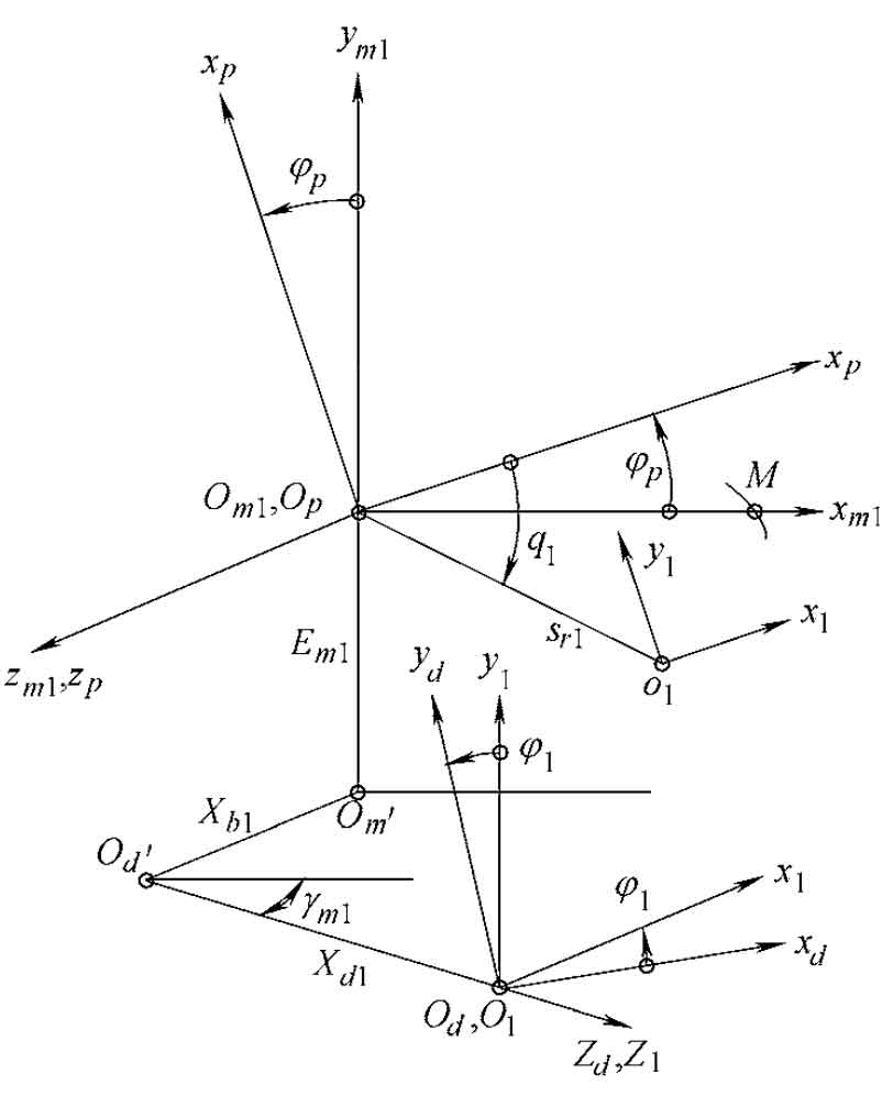
According to the production principle of spiral bevel gear pinion, the coordinate system shown in the figure is established to describe the production process of spiral bevel gear pinion. The origin ot of the cutter head coordinate system st (otxtytzt) is the cutter head center, otxtyt is the cutter tip plane (coincident with the machine tool plane), and is fixedly connected with the shaking table coordinate system sp (opxpypzp), and each coordinate axis is correspondingly parallel. The polar coordinates (Q1, Sr1) of OT in the coordinate system SP are angular tool position and radial tool position. The initial position of SP coincides with the machine tool coordinate system SM1 (om1xm1ym1zm1), and any instantaneous rotation angle relative to sp ϕ p. Then the corresponding angle of the small wheel is ϕ 1, i.e ϕ p= ϕ 1·mp1。 Other parameters γ M1 is the installation angle of the wheel blank (equal to the cone angle of the small wheel root), xb1 = | om ′ OD ′ is the bed, EM1 = | om1om ′ is the vertical wheel position, and XD1 = | OD ′ O1 | is the axial wheel position correction value. The equation of profile wheel of spiral bevel gear pinion can be described as:
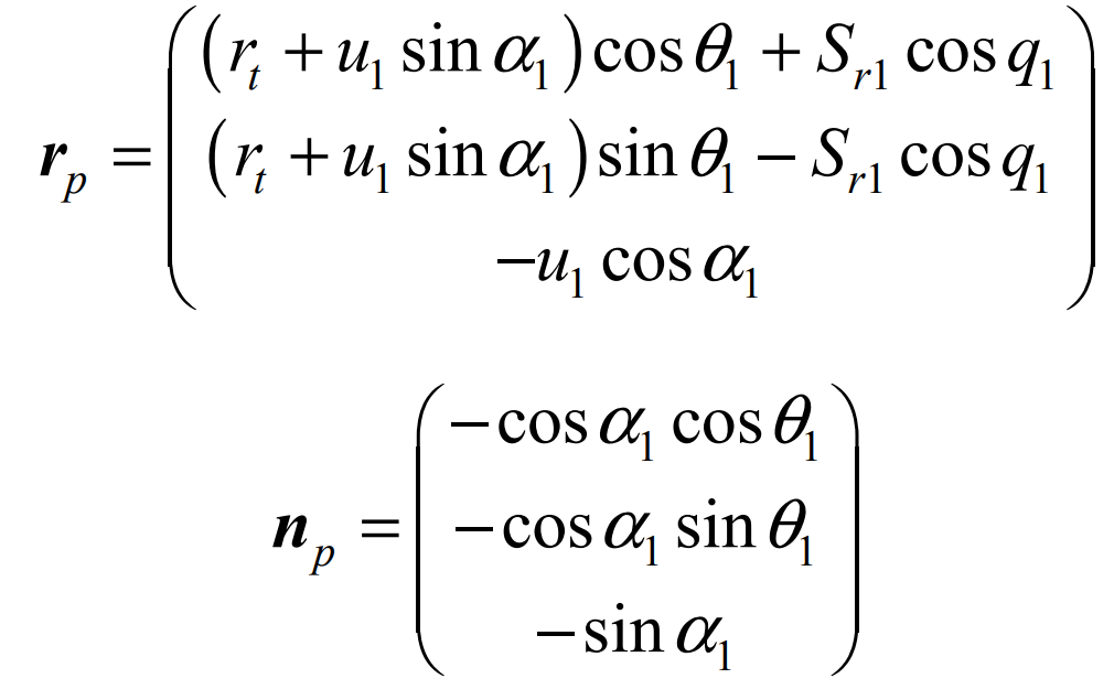
Where U1 and θ 1 is the surface parameter, RT is the tool tip radius, α 1 is the tooth profile angle of the cutter head (positive for the outer cutter and negative for the inner cutter).
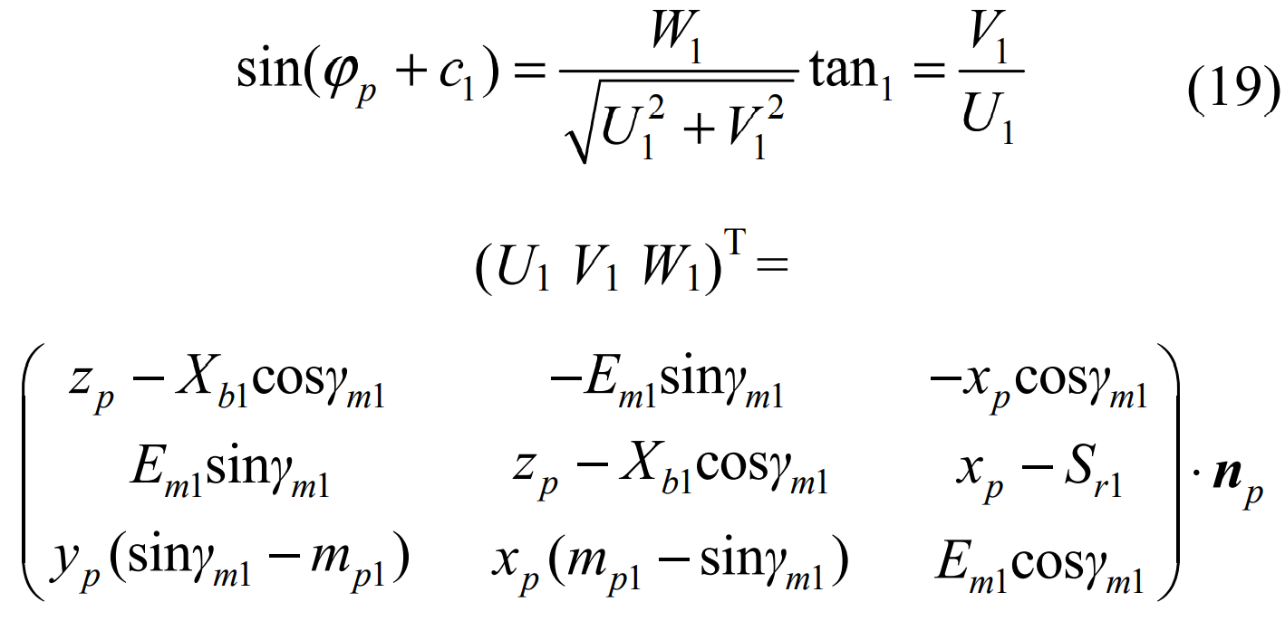
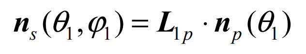
According to the corresponding parameters in the coordinate system in the figure, it can be deduced from the meshing equation of spiral bevel gear:
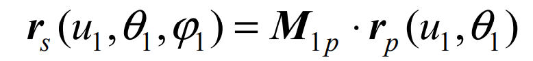
After completing the M1P homogeneous coordinate change and l1p rotation coordinate transformation from the corresponding SP coordinate system to S1, the tooth surface of the spiral bevel gear pinion can be determined Σ Equation of P: