
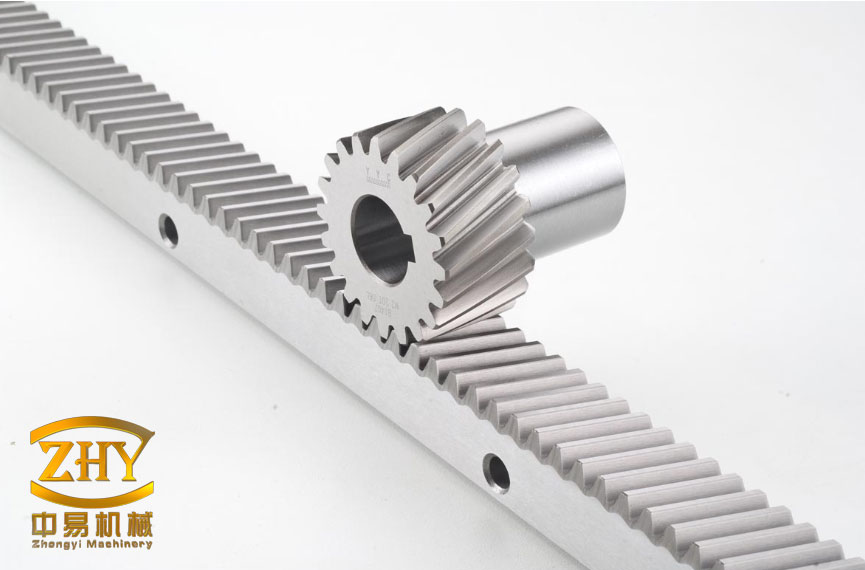
I designed this smart energy-storing speed hump because I believe a speed-control device should do more than force a vehicle to slow down. In my design, every vehicle that passes over the hump transfers a small amount of mechanical energy into a rack and pinion gear, a speed-increasing gear train, a generator, a power-conditioning circuit, and a battery. I use the same rack and pinion gear motion to estimate vehicle speed, vehicle weight, and traffic flow. My intention is to create a green, safe, comfortable, low-noise, and modular roadside product that can be deployed in cities, campuses, industrial parks, toll zones, parking facilities, and emergency-response areas. The rack and pinion gear is the heart of my mechanism because it converts linear displacement into rotary motion with simple geometry, predictable force transmission, and strong compatibility with standard machine elements.
I begin my analysis from the energy system context. Energy storage is no longer only a utility-scale topic. I see it as a distributed infrastructure problem. A speed hump is a very small energy source compared with a power plant, but it is located exactly where vehicles already lose energy. I do not need to build a new road or a new traffic-control point to recover a fraction of that loss. I only need to integrate a rack and pinion gear mechanism into a speed hump and connect it to a storage module. In my view, this distributed energy recovery approach is attractive because it is local, visible, and modular. The following table summarizes the broad energy transition direction that motivates my work.
| Indicator | 2030 Target in My Assumption | 2050 Target in My Assumption |
|---|---|---|
| Total primary energy consumption in standard coal equivalent | 60.0 hundred million tons | 55.0 hundred million tons |
| Non-fossil energy share in primary energy | 28.6 percent | 61.0 percent |
| Renewable energy share in primary energy | 23.3 percent | 47.7 percent |
| Non-fossil electricity generation share | 50 percent or higher | More than half |
I use these targets as a background signal rather than as a direct design constraint. My product does not replace large-scale generation, transmission, or storage. Instead, I position it as an edge energy device. The energy recovered by one vehicle is small, but the number of vehicle passages over a busy speed hump can be large. I therefore evaluate my design with three questions. First, can I recover energy without making the speed hump uncomfortable? Second, can I use a rack and pinion gear and a speed-increasing gear train to reach generator speed within a very short vertical stroke? Third, can I collect useful traffic data without adding expensive or invasive sensors? My answer to all three questions is yes, provided that I design the rack and pinion gear, the gear train, the generator, and the control electronics as one integrated system.
I also study the existing speed hump problem carefully. A conventional speed hump is a rigid obstacle. It creates a sharp vertical acceleration, and it converts vehicle kinetic energy into heat, noise, and vibration. That conversion is not useful to anyone. It damages suspension components, reduces passenger comfort, and can produce strong noise near residential buildings. In some places, speed humps are too high, too wide, or too densely spaced. A driver may slow down, but the vehicle still receives a hard impact. I do not want to copy that behavior. I want to replace the rigid impact with a controlled displacement. The rack and pinion gear allows me to convert that controlled displacement into rotation, and the speed-increasing gear train allows me to drive a small generator efficiently. The following table compares the conventional approach with my proposed approach.
| Criterion | Conventional Speed Hump | My Energy-Storing Speed Hump |
|---|---|---|
| Primary function | Force speed reduction | Force speed reduction and recover energy |
| Vehicle impact | Rigid, sudden, sometimes harsh | Buffered and guided by a rack and pinion gear mechanism |
| Energy use | Lost as heat, noise, and vibration | Converted into electricity and stored in a battery |
| Data collection | Usually none | Speed, weight, and traffic flow can be estimated |
| Maintenance | Simple but often damaged by impact | Modular, with replaceable rack and pinion gear and generator modules |
| Noise | Can be high | Reduced by controlled motion and damping |
| Comfort | Low | Improved through displacement and spring return |
| Expandability | Limited | High because the design is modular and sensor-ready |
My design purpose follows directly from that comparison. I want a speed hump that performs its traffic-calming duty while reducing vehicle damage and improving passenger comfort. I want it to recover energy from the vehicle passage. I want it to resist external weather and road contamination. I want it to be maintainable without removing the entire road surface. I also want it to support optional measurement modules. I therefore define my design criteria in the table below.
| Design Criterion | My Requirement | How I Meet It |
|---|---|---|
| Speed control | Encourage safe crossing speed | Controlled vertical displacement and visible hump profile |
| Comfort | Reduce sharp impact | Spring return, guided motion, and rack and pinion gear transmission |
| Energy recovery | Store usable electricity | Speed-increasing gear train, generator, rectifier, and battery |
| Safety | No exposed moving parts | Sealed box and covered linear guides |
| Durability | Resist water, dust, and salt | Sealed enclosure, corrosion-resistant materials, and drainage |
| Maintainability | Replace modules quickly | Modular rack and pinion gear, generator, and storage units |
| Data function | Estimate speed, weight, and flow | Voltage, current, and timing analysis from the generator output |
| Cost | Use standard parts where possible | Standard gears, bearings, springs, and fasteners |
My design idea is to place a mechanical energy converter inside a speed hump body. When a vehicle wheel presses the hump downward, the hump does not simply compress a rubber block. It moves a push rod linkage. The push rod linkage rotates a lever, and the lever drives a rack. The rack then rotates a pinion. This is the first rack and pinion gear stage. The rack and pinion gear transforms linear motion into rotation. Because the vertical stroke of a speed hump is limited, the pinion rotation is slow. I therefore connect the pinion shaft to a multi-stage speed-increasing gear train. The gear train raises the rotational speed to a level suitable for a small generator. The generator produces electricity, which is rectified, conditioned, and stored in a battery. A return spring restores the rack and the hump after the vehicle passes. The same rack and pinion gear motion generates a voltage pulse that I can analyze for speed, weight, and traffic flow.
I pay special attention to the rack and pinion gear because it determines the quality of the entire energy conversion. A rack and pinion gear is simple, but it is not trivial. I must choose the pinion radius, the rack length, the pressure angle, the module, the face width, the material, and the heat treatment. I must also guide the rack so that it does not jam. I must provide a return path for the rack. I must protect the rack and pinion gear from dust and water. I must consider bidirectional traffic. If vehicles pass from either direction, the rack may move in opposite directions. I can solve this with a symmetric linkage, or I can use one-way clutches so that the generator always turns in the same direction. In my preferred configuration, I use two opposing rack and pinion gear inputs or a ratcheting mechanism. This keeps the generator rotation unidirectional and simplifies the power electronics.
I describe the mechanical structure in terms of three subsystems. The first subsystem is the energy production mechanism. It includes the moving hump plate, the push rod, the pivot lever, the rack and pinion gear, the linear guide, and the return spring. The second subsystem is the speed-increasing transmission. It includes the pinion shaft, two or three gear stages, bearings, and the generator shaft coupling. The third subsystem is the storage and control unit. It includes the generator, rectifier, DC-DC converter, charge controller, battery, protection circuit, and optional data module. I place all three subsystems inside a sealed box. The box is anchored to the road foundation. The top surface is the visible speed hump. The internal space is protected from rain, dust, and debris. I also leave enough room for future sensors and communication modules.
| Subsystem | Main Parts | Function |
|---|---|---|
| Energy production mechanism | Hump plate, push rod, pivot lever, rack, pinion, guide, return spring | Convert vertical wheel motion into rack and pinion gear rotation |
| Speed-increasing transmission | Pinion shaft, spur gears, bearings, coupling | Raise low pinion speed to generator speed |
| Storage and control unit | Generator, rectifier, DC-DC converter, charge controller, battery, fuse | Convert, regulate, and store electrical energy |
| Data module | Voltage sensor, current sensor, timer, microcontroller, optional communication | Estimate speed, weight, and traffic flow |
| Enclosure | Steel or composite box, seals, drainage channels, anchor bolts | Protect internal parts and maintain road alignment |
I now explain the rack and pinion gear kinematics. Let the vertical displacement of the hump plate be y. Let the linkage ratio be i_l. The rack displacement x_r is proportional to y. I write this as a display equation.
$$ x_r = i_l y $$
The rack velocity v_r is therefore proportional to the hump vertical velocity v_h.
$$ v_r = i_l v_h $$
The pinion angular displacement theta_p depends on the rack displacement and the pinion pitch radius r_p.
$$ \theta_p = \frac{x_r}{r_p} = \frac{i_l y}{r_p} $$
The pinion angular velocity omega_p is the rack velocity divided by the pinion pitch radius.
$$ \omega_p = \frac{v_r}{r_p} = \frac{i_l v_h}{r_p} $$
The torque at the pinion depends on the rack force F_r and the pinion pitch radius.
$$ T_p = F_r r_p $$
These equations show why the rack and pinion gear is so useful in my design. The rack and pinion gear gives me a direct relationship between linear displacement and angular displacement. I can choose the pinion radius to balance stroke, speed, and torque. A smaller pinion produces more rotation for the same rack stroke, but it also reduces torque capacity. A larger pinion produces more torque, but it requires a larger rack stroke or a higher gear ratio. I therefore treat the rack and pinion gear as the first stage of my transmission design, not as an isolated component.
The following table lists the main rack and pinion gear variables that I use in my calculations.
| Symbol | Meaning | Typical Range or Unit |
|---|---|---|
| x_r | Rack linear displacement | 0.01 to 0.08 m |
| v_r | Rack linear velocity | 0.02 to 0.30 m/s |
| r_p | Pinion pitch radius | 0.015 to 0.050 m |
| theta_p | Pinion angular displacement | rad |
| omega_p | Pinion angular velocity | rad/s |
| T_p | Pinion torque | N m |
| F_r | Rack force | 100 to 5000 N |
| i_l | Linkage ratio | 0.5 to 3.0 |
Because the pinion speed is low, I must increase speed before the generator. I use a multi-stage gear train. For each stage, I define the speed ratio as the number of teeth on the driving gear divided by the number of teeth on the driven gear. If the driving gear is larger than the driven gear, the stage increases speed. The total speed ratio i_t is the product of all stage ratios.
$$ i_t = \prod_{k=1}^{n} \frac{Z_{driver,k}}{Z_{driven,k}} $$
The generator angular velocity omega_g is the pinion angular velocity multiplied by the total speed ratio.
$$ \omega_g = i_t \omega_p = i_t \frac{i_l v_h}{r_p} $$
If I prefer rotational speed in revolutions per minute, I use the following conversion.
$$ n_g = \frac{30}{\pi} \omega_g $$
The torque is inversely related to the speed ratio, with an efficiency term eta_t.
$$ T_g = \frac{T_p \eta_t}{i_t} $$
The rack force can also be expressed in terms of generator torque if I measure current and estimate torque.
$$ F_r = \frac{T_p}{r_p} = \frac{T_g i_t}{\eta_t r_p} $$
I use these equations to choose the gear stages. A single stage cannot provide a large speed increase without becoming physically large. I prefer two or three stages. For example, I can use a first stage ratio of 3, a second stage ratio of 3, and a third stage ratio of 3. The total ratio is 27. If the pinion speed is 30 rpm, the generator speed becomes 810 rpm. That is enough for a small permanent-magnet generator. The table below shows an example gear train.
| Stage | Driver Teeth | Driven Teeth | Stage Speed Ratio | Cumulative Ratio |
|---|---|---|---|---|
| Stage 1 | 36 | 12 | 3.0 | 3.0 |
| Stage 2 | 30 | 10 | 3.0 | 9.0 |
| Stage 3 | 24 | 8 | 3.0 | 27.0 |
I also calculate the mechanical power delivered by the moving hump. If the wheel applies vertical force F_y and the hump moves downward with velocity v_h, the mechanical power entering the linkage is given by the following equation.
$$ P_m = F_y v_h $$
The electrical power output is lower because of mechanical efficiency eta_m, linkage efficiency eta_l, transmission efficiency eta_t, generator efficiency eta_g, and conversion efficiency eta_c.
$$ P_e = \eta_m \eta_l \eta_t \eta_g \eta_c F_y v_h $$
I can combine these into a single system efficiency eta_sys.
$$ \eta_{sys} = \eta_m \eta_l \eta_t \eta_g \eta_c $$
Therefore, the electrical power output is simplified as follows.
$$ P_e = \eta_{sys} F_y v_h $$
The recovered energy for one vehicle passage is the integral of electrical power over the contact time t_c.
$$ E_e = \int_0^{t_c} P_e dt = \int_0^{t_c} \eta_{sys} F_y v_h dt $$
For a first-order estimate, I replace the integral with an average force and a maximum vertical stroke h.
$$ E_e \approx \eta_{sys} F_{avg} h N_a $$
In this equation, N_a is the number of axles that cross the hump. I use this equation because it is simple enough for early design and accurate enough for sizing the generator and battery. I can refine it with a dynamic model later. The table below shows an example calculation for a passenger car.
| Parameter | Symbol | Example Value |
|---|---|---|
| Average vertical force per axle | F_avg | 2500 N |
| Vertical stroke | h | 0.04 m |
| Number of axles | N_a | 2 |
| System efficiency | eta_sys | 0.35 |
| Recovered energy | E_e | 70 J |
A single passage therefore provides only a small amount of energy. I do not hide that fact. My design is not a replacement for a power station. Its value comes from repetition, distributed placement, and additional data services. If a speed hump is crossed by 10,000 vehicles per day, the daily energy can become meaningful for low-power roadside loads. I calculate the daily energy as follows.
$$ E_{day} = N_{day} E_e $$
If I use the example value of 70 J per passage and 10,000 passages per day, the daily energy is 700,000 J, which is about 0.194 kWh. That is enough for low-power sensors, small lights, or emergency backup support. If I improve the mechanism and use larger vehicles, the value can increase. I therefore design the storage unit to be modular. I can add more battery capacity or more generator modules when traffic volume is high. The table below summarizes my energy-selection logic.
| Traffic Level | Passages per Day | Typical Daily Energy in My Example | Recommended Storage |
|---|---|---|---|
| Low | 500 | 0.010 kWh | Small battery or supercapacitor |
| Medium | 5,000 | 0.097 kWh | Medium battery module |
| High | 10,000 | 0.194 kWh | Larger battery module |
| Very high | 30,000 | 0.583 kWh | Multiple battery modules |
I also consider the generator and storage equations. For a permanent-magnet generator, the induced voltage E_g is proportional to angular velocity omega_g through the voltage constant K_e.
$$ E_g = K_e \omega_g $$
The electromagnetic torque T_g is proportional to current I_g through the torque constant K_t.
$$ T_g = K_t I_g $$
For an ideal machine, K_e and K_t are numerically related within a consistent unit system. I use this relationship to estimate force from current. The electrical power output before conversion losses is the product of voltage and current.
$$ P_e = E_g I_g $$
The battery charging power P_b is reduced by rectifier and converter efficiency eta_c.
$$ P_b = \eta_c E_g I_g $$
The stored energy over a time interval is the integral of charging power.
$$ E_b = \int_0^{t} P_b dt $$
If the battery has rated capacity C_b and nominal voltage V_b, the usable energy is approximately as follows.
$$ E_{usable} \approx C_b V_b DOD $$
In this expression, DOD is the depth of discharge that I allow for battery life. I prefer lithium iron phosphate cells or a hybrid battery-supercapacitor design because they tolerate frequent partial charging. I also include overvoltage protection, overcurrent protection, reverse-polarity protection, and thermal protection. The following table lists the electrical design targets that I set for my prototype.
| Electrical Parameter | My Target | Reason |
|---|---|---|
| Generator type | Permanent-magnet DC or three-phase AC with rectifier | High efficiency at small size |
| Generator speed | 600 to 1500 rpm | Usable voltage at low vehicle speed |
| Rectifier | Bridge rectifier or active rectifier | Convert AC to DC when needed |
| DC-DC converter | Buck-boost or charge controller | Match generator output to battery voltage |
| Battery chemistry | LiFePO4 or supercapacitor hybrid | Cycle life and safety |
| Nominal battery voltage | 12 V or 24 V | Compatibility with roadside loads |
| Protection | Fuse, TVS, reverse protection, thermal cutoff | Safety and reliability |
I now describe the working sequence in detail. When a vehicle approaches, the driver sees the speed hump and slows down. When the wheel contacts the hump plate, the plate moves downward. The push rod transmits this motion to a pivot lever. The pivot lever pushes the rack horizontally. The rack rotates the pinion. The pinion shaft drives the speed-increasing gear train. The gear train drives the generator. The generator produces a voltage pulse. The rectifier and converter charge the battery. After the wheel passes, the return spring pushes the rack back to its original position. The hump plate rises to its original profile. The system is ready for the next vehicle. If the vehicle passes in the opposite direction, a symmetric rack and pinion gear input or a one-way clutch rectifies the motion so that the generator continues to rotate in the same direction.
I use the phrase rack and pinion gear repeatedly in my design notes because every major behavior depends on it. The rack and pinion gear sets the input speed. The rack and pinion gear sets the input torque. The rack and pinion gear determines the stroke-to-rotation ratio. The rack and pinion gear also creates a repeatable voltage waveform. I can analyze that waveform to estimate vehicle speed. I can analyze its amplitude to estimate vehicle weight. I can count its pulses to estimate traffic flow. This is why I do not treat the rack and pinion gear as a mere mechanical detail. It is the sensing element as well as the transmission element.
For speed estimation, I use the duration of the generator pulse. If the contact length of the hump is L_c and the pulse duration is t_p, the vehicle speed is approximately as follows.
$$ v \approx \frac{L_c}{t_p} $$
I can also use the peak voltage. Because the induced voltage is proportional to generator speed, and generator speed is proportional to rack speed, the peak voltage is proportional to vehicle speed.
$$ V_{peak} = K_e \omega_g = K_e i_t \frac{i_l v_h}{r_p} $$
If I know the linkage ratio, the gear ratio, the pinion radius, and the generator constant, I can invert this relationship to estimate the rack velocity.
$$ v_r = \frac{V_{peak} r_p}{K_e i_t} $$
I then relate rack velocity to vehicle speed through the hump geometry. If the hump has an effective slope angle alpha, the vertical velocity v_h is related to the horizontal vehicle speed v_x.
$$ v_h = v_x \tan \alpha $$
Therefore, the vehicle speed estimate becomes as follows.
$$ v_x = \frac{v_r}{i_l \tan \alpha} $$
In practice, I combine the timing method and the voltage method. The timing method is robust for slow speed. The voltage method is useful for higher speed. I use a simple data-fusion rule to reduce error. The table below shows the speed-estimation logic I would implement.
| Measurement | Primary Use | Advantage | Limitation |
|---|---|---|---|
| Pulse duration t_p | Estimate speed | Simple and low cost | Depends on contact length |
| Peak voltage V_peak | Estimate speed or weight trend | Fast response | Affected by generator constant and load |
| Current integral | Estimate energy and load | Directly related to torque | Requires current sensing |
| Multiple hump modules | Improve weight estimate | Reduces speed dependence | Higher installation cost |
For weight estimation, I use the generator current. The electromagnetic torque is proportional to current. The rack force is proportional to generator torque and gear ratio. Therefore, the axle load can be estimated from current. The following equations show my approach.
$$ T_g = K_t I_g $$
$$ F_r = \frac{T_g i_t}{\eta_t r_p} = \frac{K_t I_g i_t}{\eta_t r_p} $$
If multiple axles cross the hump, I sum the estimated forces.
$$ W = \sum_{j=1}^{N_a} F_{r,j} $$
I know that speed variation affects the current waveform. A fast vehicle produces a shorter pulse, while a slow vehicle produces a longer pulse. I therefore normalize the weight estimate with speed. I can use a calibration function f(v).
$$ \hat{W} = \frac{W}{f(v)} $$
I calibrate f(v) with known test vehicles. I also use multiple hump modules in a short section. The front axle and rear axle pass over different modules at different times. The time difference and the current amplitude help me separate speed from weight. The table below lists my data outputs and how I use them.
| Data Output | Physical Basis | Application |
|---|---|---|
| Pulse count | Rack and pinion gear rotation events | Traffic flow |
| Pulse duration | Contact time | Speed estimation |
| Peak voltage | Generator speed | Speed trend and event detection |
| Current amplitude | Generator torque | Weight estimation |
| Energy per event | Integrated power | Energy accounting and maintenance warning |
| Time of day | Real-time clock | Traffic pattern analysis |
For traffic flow, I define the flow rate Q as the number of vehicles N divided by the observation interval delta t.
$$ Q = \frac{N}{\Delta t} $$
I define density rho as flow divided by average speed.
$$ \rho = \frac{Q}{\bar{v}} $$
The average speed is the arithmetic mean of individual speed estimates.
$$ \bar{v} = \frac{1}{N} \sum_{i=1}^{N} v_i $$
The average weight is the arithmetic mean of individual weight estimates.
$$ \bar{W} = \frac{1}{N} \sum_{i=1}^{N} W_i $$
I use these values to support traffic management. For example, if the average speed is too high, I can recommend stronger speed-control measures. If the average weight is too high, I can recommend road maintenance or load enforcement. If the flow rate is very high, I can recommend signal timing or lane management. I do not need cameras or personally identifiable information. I only need the mechanical response of the rack and pinion gear and the electrical response of the generator.
My product functions can be grouped into five practical modes. The first mode is fixed energy supply. The battery can power roadside lights, signs, sensors, or small communication nodes. The second mode is emergency power. In a blackout or natural disaster, the battery can be removed and used as a portable emergency source. The third mode is speed measurement. The system can detect speeding and notify traffic authorities. The fourth mode is weight measurement. The system can detect overload and notify traffic authorities. The fifth mode is traffic flow detection. The system can count vehicles and provide data for road planning. The table below summarizes these functions.
| Function Mode | Description | Benefit |
|---|---|---|
| Fixed energy supply | Charge battery from vehicle passages and power roadside loads | Lower cable cost and lower maintenance |
| Emergency power | Use removable battery during outages or disasters | Rapid local power support |
| Speed measurement | Estimate speed from pulse duration and voltage | Support speed enforcement and safety |
| Weight measurement | Estimate axle load from current amplitude | Support overload detection |
| Traffic flow detection | Count passages and analyze time patterns | Support traffic planning and diversion |
I also consider the physical environment. A speed hump is exposed to rain, snow, dust, salt, oil, and temperature change. I therefore design the enclosure with drainage channels, sealing gaskets, and corrosion-resistant fasteners. I use stainless steel or coated steel for the rack and pinion gear components. I use sealed bearings. I apply grease that remains stable across a wide temperature range. I protect the generator with a splash shield. I make the top plate removable so that maintenance can be performed without excavating the entire foundation. I also design the rack and pinion gear chamber as a separate module. If the rack and pinion gear wears out, I can replace it as a unit. This reduces downtime and keeps the installation cost predictable.
| Environmental Risk | Effect on My Design | Mitigation |
|---|---|---|
| Water ingress | Rust and electrical short | Seals, drainage, IP-rated enclosure |
| Dust and sand | Wear in rack and pinion gear | Wipers, sealed guide, periodic cleaning |
| Salt | Corrosion | Coated rack, stainless fasteners |
| Temperature change | Thermal expansion and grease thickening | Clearances and wide-temperature lubricant |
| Heavy vehicle impact | Overload and fatigue | Stops, springs, and safety factor |
| Vibration | Loose fasteners | Thread locking and periodic inspection |
I also check the mechanical strength of the rack and pinion gear. The bending stress in a gear tooth must remain below the allowable stress. I use the standard Lewis equation as a first estimate.
$$ \sigma_b = \frac{F_t}{b m Y} $$
In this equation, F_t is the tangential force, b is the face width, m is the module, and Y is the Lewis form factor. I then apply a safety factor S_f.
$$ \sigma_{allow} = \frac{\sigma_y}{S_f} $$
I check that the bending stress is less than the allowable stress.
$$ \sigma_b \leq \sigma_{allow} $$
I also check contact stress. For a preliminary estimate, I use the Hertzian contact relationship.
$$ \sigma_c = Z_E \sqrt{\frac{F_t}{b d_1} \frac{u+1}{u}} $$
In this expression, Z_E is the elastic coefficient, d_1 is the pinion pitch diameter, and u is the gear ratio. I increase face width or surface hardness if the contact stress is too high. I also check the rack guide for buckling and wear. Because the rack stroke is short, I can use a compact linear guide with recirculating balls or a plain bearing with low friction. I prefer a sealed linear guide for long life. The table below lists my mechanical design checks.
| Check | Equation or Rule | Design Action |
|---|---|---|
| Gear tooth bending | Lewis equation | Increase module or face width |
| Gear tooth contact | Hertzian contact estimate | Increase hardness or face width |
| Rack buckling | Euler buckling check | Increase rack cross section or support length |
| Bearing life | L10 life calculation | Select larger bearing or reduce load |
| Spring fatigue | Goodman diagram | Use chrome-silicon spring wire and shot peening |
| Enclosure stiffness | Deflection limit | Add ribs or increase plate thickness |
I consider the vehicle dynamics as well. When a wheel crosses the hump, the vertical force is not constant. It depends on suspension stiffness, damping, vehicle mass, speed, and hump profile. I can model the vehicle as a quarter-car system. The sprung mass m_s and unsprung mass m_u are connected by suspension stiffness k_s and damping c_s. The tire stiffness is k_t. The hump profile y_r(t) acts as a road input. The equations of motion are as follows.
$$ m_s \ddot{z}_s + c_s (\dot{z}_s – \dot{z}_u) + k_s (z_s – z_u) = 0 $$
$$ m_u \ddot{z}_u + c_s (\dot{z}_u – \dot{z}_s) + k_s (z_u – z_s) + k_t (z_u – y_r) = 0 $$
I use this model to estimate the force transmitted to my rack and pinion gear. The model also helps me tune the spring return and the damping of the hump plate. I do not want the hump plate to oscillate after the vehicle passes. I want it to return smoothly and quickly. I therefore add a damping element or a frictional damper. The rack and pinion gear must not be subjected to shock loads beyond its design limit. I use mechanical stops to limit the maximum stroke. I use a preload spring to keep the rack in contact with the pinion. I use a guide rail to prevent skew. These details are important because a rack and pinion gear can jam if it is misaligned or contaminated.
My design also supports modular deployment. I can install one module for a narrow lane. I can install multiple modules across a wide road. I can connect the batteries in parallel or keep them independent. If one module fails, the others continue to operate. I can also mix functions. For example, a school zone may prioritize speed control and pedestrian safety. A logistics park may prioritize weight measurement and energy recovery. A highway service area may prioritize traffic flow and emergency power. The table below shows how I match functions to locations.
| Location | Primary Function | Secondary Function | Recommended Module Configuration |
|---|---|---|---|
| School zone | Speed control | Traffic flow | Single or double module with low stroke |
| Residential street | Noise reduction | Energy recovery | Damped module with sealed rack and pinion gear |
| Industrial park | Weight measurement | Energy recovery | Heavy-duty module with multiple sensors |
| Parking facility | Energy recovery | Traffic counting | Compact module with battery storage |
| Toll zone | Speed and flow | Weight trend | Networked modules with data logging |
| Emergency route | Emergency power | Traffic monitoring | Removable battery module |
I also compare my design with other energy-harvesting speed humps. Some designs use piezoelectric elements. Some use hydraulic systems. Some use electromagnetic dampers. Each has advantages. Piezoelectric systems are compact but produce low power and are expensive for large displacement. Hydraulic systems can transmit high force but add complexity, fluid maintenance, and leakage risk. Electromagnetic dampers can be efficient but require careful control. My rack and pinion gear design is mechanical, visible, and easy to understand. It uses standard gears and bearings. It can be repaired with common tools. It also provides a clear mechanical signal for speed and weight estimation. I do not claim that my design is best for every case, but I claim that it is a strong option for distributed roadside energy recovery and traffic data collection.
| Technology | Advantage | Disadvantage | My Assessment |
|---|---|---|---|
| Piezoelectric | Compact, no large moving parts | Low power, high cost, limited stroke | Good for sensors, not for bulk recovery |
| Hydraulic | High force density | Leakage, maintenance, complexity | Good for heavy systems but not preferred for my modular hump |
| Electromagnetic damper | Controllable, smooth | Complex power electronics | Good for active suspension, less simple for roadside |
| Rack and pinion gear | Simple, robust, direct linear-to-rotary conversion | Needs sealing and alignment | My preferred core mechanism |
I also evaluate the economic value. The cost of my system includes the hump structure, the rack and pinion gear, the gear train, the generator, the battery, the controller, the sensors, and installation. The revenue or savings include reduced roadside wiring, reduced maintenance of conventional speed humps, local power for signs and sensors, emergency backup value, and data value. I do not need the system to pay back solely through electricity sales. The data function and safety function can justify the investment. In many locations, the cost of trenching and cabling for a single roadside sensor is higher than the cost of a small energy-storing hump. My design can avoid that trenching cost by generating its own power. The table below shows my qualitative cost-benefit logic.
| Cost Item | Driver | Reduction Strategy |
|---|---|---|
| Mechanical structure | Material and fabrication | Standard profiles and modular plates |
| Rack and pinion gear | Precision and material | Standard module, optimized face width |
| Gear train | Number of stages | Use two or three efficient stages |
| Generator | Power rating | Match generator to average traffic, not peak |
| Battery | Capacity and chemistry | Use LiFePO4 or hybrid storage |
| Control electronics | Functions | Start with basic protection and add data later |
| Installation | Road work | Preassembled modules and standard anchors |
| Maintenance | Inspection and replacement | Sealed rack and pinion gear and quick-change modules |
I also consider safety and reliability. The system must not create a tripping hazard, an electrical hazard, or a road hazard. The top plate must be flush with the road when at rest. The moving parts must be covered. The electrical compartment must be grounded and fused. The battery must be protected from overcharge, overdischarge, short circuit, and overheating. The rack and pinion gear must have mechanical stops. The return spring must be captive so that it cannot escape if it breaks. The enclosure must withstand vehicle loads without permanent deformation. I use a fail-safe design: if the generator or battery fails, the speed hump still acts as a passive speed-control device. If the rack and pinion gear jams, the top plate remains supported by the enclosure and does not collapse. These requirements are part of my design from the beginning, not added later.
| Hazard | Cause | My Control |
|---|---|---|
| Electrical shock | Damaged cable or water ingress | Grounding, insulation, IP-rated enclosure, fuse |
| Battery fire | Overcharge or short circuit | BMS, thermal cutoff, fused output |
| Mechanical jam | Debris in rack and pinion gear | Seals, wipers, inspection window |
| Spring failure | Fatigue | Captive spring, safety factor, periodic replacement |
| Top plate sinking | Foundation failure | Reinforced box, anchor bolts, load distribution |
| Pedestrian trip | Uneven surface | Flush rest position, chamfered edges, visible marking |
I also think about maintenance. A roadside device must be easy to inspect. I design the enclosure with a removable top cover and a sealed electrical bay. I use a rack and pinion gear module that can be removed after disconnecting the coupling. I use a generator module that can be replaced without opening the gearbox. I use a battery module that can be swapped in minutes. I schedule inspection based on traffic volume. Low-traffic sites may need annual inspection. High-traffic sites may need quarterly inspection. I monitor generator current and voltage to detect changes in friction, alignment, or battery health. If the current waveform changes, I can schedule maintenance before a failure occurs. The table below shows my maintenance plan.
| Interval | Task | Purpose |
|---|---|---|
| Monthly remote check | Review voltage, current, and energy logs | Detect abnormal trends |
| Quarterly visual check | Inspect top plate, seals, and drainage | Prevent water and debris damage |
| Every six months | Check rack and pinion gear lubrication | Reduce wear and friction |
| Annually | Check fasteners, spring, and electrical connections | Ensure mechanical and electrical safety |
| Every three to five years | Replace battery or bearing module | Maintain performance |
| As needed | Replace rack and pinion gear module | Restore transmission efficiency |
I also consider data privacy. My design does not require cameras, license plate recognition, or personal data. It measures mechanical and electrical signals. It can count vehicles, estimate speed, estimate weight, and analyze traffic flow without identifying drivers. This is a major advantage in public spaces. I can transmit only aggregated data, such as vehicles per hour or average speed. If the system is connected to a network, I can encrypt the data and limit access. I can also store data locally and upload only summaries. This approach respects privacy while still providing useful traffic information.
I also consider scalability. I can start with a single prototype and then expand. The rack and pinion gear module can be scaled in width and stroke. The gear train can be scaled in ratio. The generator can be scaled in power. The battery can be scaled in capacity. The control software can be scaled in functions. This means I can design a family of products: a light-duty model for campuses, a medium-duty model for city streets, and a heavy-duty model for industrial roads. The table below shows my scaling logic.
| Model | Typical Application | Rack and Pinion Gear Size | Generator Power | Battery Capacity |
|---|---|---|---|---|
| Light duty | Campus, parking lot | Small module | 10 to 30 W | Small 12 V battery |
| Medium duty | City street, residential zone | Medium module | 30 to 100 W | Medium 12 V or 24 V battery |
| Heavy duty | Industrial road, logistics park | Large module | 100 to 300 W | Large 24 V battery bank |
| Networked | Toll zone, arterial road | Multiple modules | 300 W or more | Shared storage and data hub |
I also model the expected performance. For a medium-duty module, I assume a vertical stroke of 40 mm, an average vertical force of 2500 N per axle, two axles, and a system efficiency of 0.35. The recovered energy per passage is about 70 J. If the hump is crossed 10,000 times per day, the daily energy is about 0.194 kWh. If the average is 0.5 kWh per day for a busy site, the annual energy is about 182.5 kWh. That is not a large amount of electricity, but it is enough for standalone low-power devices. More importantly, the system provides data and safety functions. I therefore evaluate success not only by kilowatt-hours but also by avoided cabling, improved traffic data, reduced vehicle damage, and emergency readiness.
I also consider the force and torque limits. If the rack force is too high, the rack and pinion gear may fail. I therefore calculate the maximum rack force from the vehicle load. For a heavy vehicle, the axle load can be much higher than a passenger car. I use a safety factor. I design the rack and pinion gear with a larger module and face width for heavy-duty applications. I also use a slip clutch or a relief mechanism to protect the generator from shock loads. The slip clutch can limit the maximum torque transmitted to the gear train. This is important because a heavy vehicle at low speed can produce a very high force. The table below shows my load cases.
| Load Case | Vehicle Type | Estimated Axle Load | Design Response |
|---|---|---|---|
| Light | Motorcycle or small car | Low | Low spring preload, small generator |
| Medium | Passenger car | Moderate | Standard rack and pinion gear module |
| Heavy | Bus or truck | High | Reinforced rack and pinion gear, slip clutch |
| Overload | Illegal overload | Very high | Mechanical stop, data alert, safety relief |
I also consider the generator choice. A permanent-magnet synchronous generator is attractive because it has high efficiency and a simple rotor. A brushed DC generator is simpler for low-cost prototypes but requires brush maintenance. A three-phase AC generator with a rectifier is robust and efficient. I prefer a three-phase permanent-magnet generator for production. I match the generator constant to the expected speed range. If the generator constant is too low, the voltage will be too low at slow speed. If it is too high, the voltage will be too high at high speed. I therefore use a DC-DC converter to regulate the output. The converter also provides maximum power point tracking if needed. The table below compares generator options.
| Generator Type | Advantage | Disadvantage | My Preference |
|---|---|---|---|
| Brushed DC | Simple, low cost | Brush wear, lower life | Prototype only |
| Permanent-magnet DC | Good low-speed output | Limited voltage range | Small modules |
| Three-phase PM AC | High efficiency, robust | Needs rectifier | Preferred for production |
| Induction generator | Rugged | Needs excitation and control | Not preferred for small roadside units |
I also consider the control algorithm. The microcontroller reads voltage and current. It detects a pulse when the voltage rises above a threshold. It records the start time, peak time, and end time. It computes pulse duration and peak voltage. It integrates power to estimate energy. It classifies the event as a light, medium, or heavy vehicle based on current and duration. It stores the event in memory. It updates the traffic count, average speed, and average weight. It controls the charging of the battery. It protects the battery from overvoltage and overdischarge. It can send a summary to a remote server if a communication module is installed. The algorithm is simple enough to run on a low-power microcontroller. The table below shows the control states.
| State | Condition | Action |
|---|---|---|
| Idle | No voltage pulse | Monitor battery and sensors |
| Event detection | Voltage above threshold | Start timer and record data |
| Energy capture | Pulse active | Rectify, convert, and charge battery |
| Classification | Pulse ended | Compute speed, weight, and energy |
| Storage | Data ready | Update counters and logs |
| Protection | Fault detected | Disconnect output and record fault |
| Communication | Scheduled or triggered | Send summary data |
I also think about the future. I can add more sensors without changing the mechanical core. I can add a temperature sensor to monitor the rack and pinion gear chamber. I can add a vibration sensor to detect abnormal wear. I can add a wireless module to connect multiple humps. I can add a solar panel to supplement the battery. I can add a small display to show recovered energy to the public. I can add a pedestrian detection sensor for school zones. The rack and pinion gear remains the central mechanical interface, and the modular design allows these upgrades. This is why I describe my design as a platform, not just a single product.
I also consider the social value. Safer roads, quieter neighborhoods, lower vehicle damage, and local emergency power are all public benefits. The data function can help traffic authorities allocate resources more efficiently. The energy function can help power roadside equipment without trenching. The modular function can be adapted to different environments. I believe these benefits justify further research and field testing. I also recognize that field testing is necessary because real roads are noisy, dirty, and unpredictable. I would test the rack and pinion gear under different speeds, loads, temperatures, and contamination conditions. I would measure efficiency, wear, and data accuracy. I would refine the design based on those results.
In my final evaluation, I summarize the core design logic with the following equations. The linear-to-rotary conversion is governed by the rack and pinion gear.
$$ \theta_p = \frac{x_r}{r_p} $$
$$ \omega_p = \frac{v_r}{r_p} $$
The speed increase is governed by the gear train.
$$ i_t = \prod_{k=1}^{n} \frac{Z_{driver,k}}{Z_{driven,k}} $$
$$ \omega_g = i_t \omega_p $$
The electrical output is governed by the generator and conversion efficiency.
$$ E_g = K_e \omega_g $$
$$ P_e = \eta_{sys} F_y v_h $$
The stored energy is governed by integration and battery capacity.
$$ E_e = \int_0^{t_c} P_e dt $$
$$ E_b = \int_0^{t} P_b dt $$
The data functions are governed by timing, voltage, and current.
$$ v \approx \frac{L_c}{t_p} $$
$$ W = \sum_{j=1}^{N_a} \frac{K_t I_{g,j} i_t}{\eta_t r_p} $$
$$ Q = \frac{N}{\Delta t} $$
I conclude that my smart energy-storing speed hump is technically feasible and practically valuable. I do not claim that it will solve all energy problems. I do claim that it can turn a necessary traffic-calming device into a multifunctional roadside asset. The rack and pinion gear provides the mechanical bridge between vehicle motion and electrical energy. The gear train provides the speed increase needed by the generator. The battery provides local storage. The data module provides traffic insight. The modular enclosure provides durability and maintainability. I believe this combination is worth developing further because it aligns with green energy, safe mobility, and intelligent city goals.
My next steps would be to build a full-scale prototype, test the rack and pinion gear under repeated cyclic loading, measure the generator output, validate the speed and weight estimation algorithms, and evaluate the system over a full year of weather conditions. I would also compare the cost with conventional speed humps and standalone roadside power systems. If the results are positive, I would deploy the design first in controlled environments such as campuses, industrial parks, and parking facilities. After that, I would move to public roads with the approval of traffic authorities. Through this process, I can improve the rack and pinion gear, the speed-increasing transmission, the generator control, and the data analysis. The final product would be a practical example of how a simple mechanical principle, the rack and pinion gear, can support energy recovery, traffic safety, and intelligent infrastructure at the same time.