
Contact fatigue failure, manifesting as pitting and spalling, is a predominant failure mode in enclosed gear transmissions, particularly for heavily loaded components like those found in vehicle drive systems. This failure mechanism leads to the progressive degradation of tooth flank topography, resulting in increased vibration, noise, and, ultimately, the risk of catastrophic tooth fracture. The etiology of contact fatigue is complex, influenced by a confluence of factors including material properties, microstructure, surface finish, contact stress magnitude, sliding friction, lubrication regime, residual stresses, and assembly accuracy. Consequently, the mechanisms underpinning this failure mode are not yet fully elucidated. In essence, contact fatigue is the culmination of cumulative damage, involving the nucleation and propagation of micro-cracks. These cracks can initiate either at the surface (surface pitting) or in the subsurface (subsurface pitting). Subsurface pitting is often associated with material discontinuities such as inclusions or voids and is typically linked to the region of maximum subsurface Hertzian shear stress. Surface pitting, on the other hand, originates from surface or near-surface defects like scratches, machining marks, or indentations, exacerbated by the intense asperity interactions and local plastic deformation inherent in rolling-sliding contact.
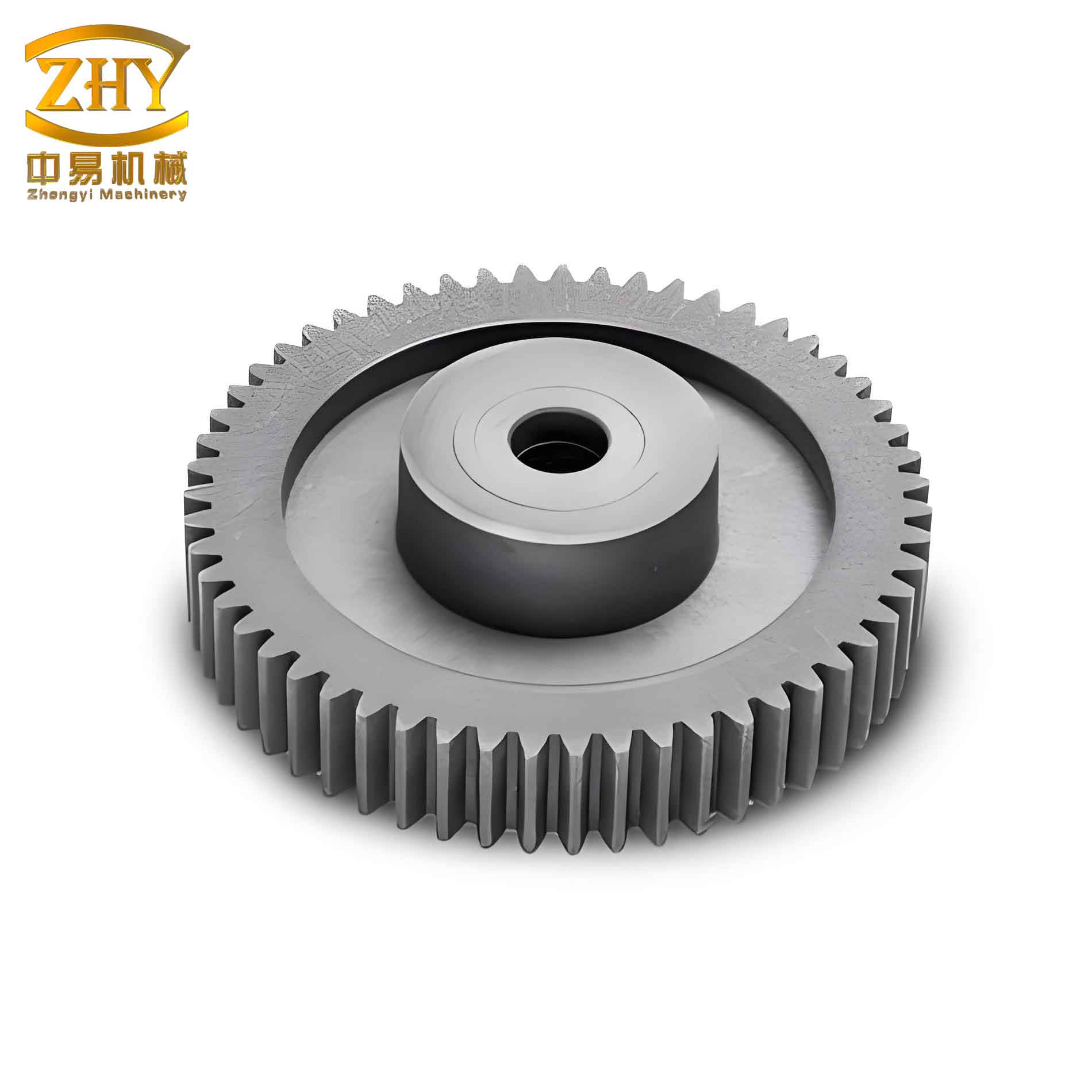
A widely observed phenomenon in spur and pinion gear failures is the preferential occurrence of fatigue damage on the dedendum (root-side) surface near the pitch line, compared to the addendum (tip-side). While this observation is empirical, its theoretical explanation remains debated. The classical Way theory attributes this to a hydrodynamic crack propagation mechanism favored by the negative sliding on the dedendum. However, subsequent fracture mechanics analyses by researchers like Keer and Bower suggest a Mode II (shear-driven) crack growth dominant in pitting, which challenges the classical view. Alternative explanations point to the higher sliding velocity and associated frictional work on the dedendum as primary drivers for surface-initiated damage. Yet, this region also experiences lower nominal contact pressure during double-tooth engagement and potentially thicker lubricant films at the initial meshing point, which should theoretically reduce fatigue susceptibility. This apparent contradiction suggests that a more nuanced, multifactorial analysis is required. This study, therefore, re-examines the origins of contact fatigue in an involute spur and pinion gear set through a synergistic approach combining detailed surface failure morphology analysis with a comprehensive finite element analysis (FEA) of the dynamic meshing process.
1. Morphological Analysis of Contact Fatigue on the Spur and Pinion Gear
The subject of this investigation is a case-hardened spur and pinion gear manufactured from 18Cr2Ni4WA steel, operating under splash lubrication in a heavy-duty vehicle transmission. A macroscopic examination of the failed pinion gear flank reveals a distinct, non-uniform distribution of contact fatigue damage, which provides critical clues linking failure morphology to the meshing cycle.
The flank can be demarcated by several characteristic lines corresponding to key transitions in the meshing sequence of a specific tooth, say tooth #2. The damage pattern is summarized as follows:
- Region A (Near Gear-In Point): Immediately following the initial point of contact, a band of relatively shallow, elongated spalling runs parallel to the gear-in line. The depth of these spalls is approximately 0.3 mm.
- Region B (First Double-Tooth Contact Zone): The dedendum surface from the end of the gear-in shock to the start of single-tooth contact is densely covered with fine, superficial pitting. This creates a distinct “grey belt” on the flank.
- Region C (Dedendum Near Pitch Line): The area on the dedendum close to the theoretical pitch line exhibits severe, large-scale spalling. These are deep pits (up to 0.8 mm) that often coalesce into extensive剥落 areas. Notably, the non-spalled areas within this region show minimal superficial pitting and have lost their original machining marks due to wear.
- Region D (Addendum Area): The addendum surface shows scattered, shallow surface pitting. The pits often align with wear scars, likely caused by abrasive debris from upstream spalling.
This highly localized damage distribution strongly suggests a direct correlation with the specific contact conditions—stress, slip, and friction—experienced at different points along the tooth flank during the meshing cycle of the spur and pinion gear. To decipher this correlation, a detailed finite element stress analysis is indispensable.
2. Finite Element Analysis of the Spur and Pinion Gear Meshing Process
To unravel the stress state responsible for the observed failure morphology, a 2D plane strain finite element model of the spur and pinion gear pair was developed using ANSYS. A full-tooth model was constructed for both gears to minimize boundary effects. The analysis focused on the complete meshing cycle of a single tooth (tooth #2). The contact surfaces were finely meshed with an element size of 0.05 mm. The model employed PLANE182 elements for the bodies, CONTA171 and TARGE169 elements for the contact pair, and used the augmented Lagrange method for contact resolution with a coefficient of friction of 0.06. Geometric nonlinearity was accounted for. Torque was applied to the pinion shaft while the gear shaft was constrained, simulating the driving condition. The analysis proceeded through numerous small increments to accurately capture the evolving contact state. Key parameters for the spur and pinion gear are: module = 7, pressure angle = 23°, pinion teeth = 17, gear ratio = 2.41.
The following normalized parameters were extracted along the tooth flank profile of tooth #2 during its meshing cycle: Contact Pressure ($p$), Relative Sliding Velocity ($v_s$), Frictional Stress ($\tau_f$), Frictional Work ($W_f$), and Subsurface Maximum Shear Stress ($\tau_{max}$) along with its depth ($z_{\tau_{max}}$). Normalization was performed relative to the maximum absolute value of each parameter during the cycle.
3. Integrated Analysis of Stress State and Failure Morphology
The FEA results provide a clear and detailed map of the mechanical conditions along the flank of the spur and pinion gear. By superimposing this map onto the observed failure morphology, the origins of the different damage modes become evident.
3.1 Characteristic Points and Meshing Phases
The analysis identifies eight characteristic points on the flank, corresponding to transitions in the meshing sequence:
- ①: Initial contact (Gear-in point).
- ②: End of gear-in impact stabilization.
- ③: Start of disengagement of the preceding tooth (tooth #1).
- ④: End of preceding tooth disengagement (Start of Single-Tooth Contact, LPSTC).
- ⑤: Theoretical pitch point.
- ⑥: Start of engagement of the following tooth (tooth #3).
- ⑦: Start of Second Double-Tooth Contact.
- ⑧: Disengagement of tooth #2.
3.2 Stress and Sliding Parameters Along the Flank
The variation of key parameters is critical for understanding spur and pinion gear failure.
Contact Pressure ($p$): The contact pressure curve shows two significant peaks associated with impact. The first occurs during gear-in (①-②). The second, and larger, peak coincides with the transition to single-tooth contact (③-④) as the load is suddenly transferred onto one pair. Pressure is highest during single-tooth contact (④-⑥) and decreases during the second double-tooth contact (⑦-⑧).
Relative Sliding ($v_s$): Sliding is negative (dedendum driving) before the pitch point and positive after. Its magnitude is highest near the gear-in point, decreases towards the pitch region, and increases again towards the tip. The region from ① to ④ experiences the most severe negative sliding.
Frictional Stress ($\tau_f$): Proportional to contact pressure and friction coefficient, frictional stress follows a similar trend to pressure but changes sign at the pitch point. Its average magnitude during the first double-tooth contact is higher than during the second.
Frictional Work ($W_f$): This parameter, representing the accumulated energy dissipation due to friction along the sliding path, is a crucial indicator for surface damage potential. It is calculated as the integral of frictional stress over sliding distance. Frictional work peaks in the initial engagement zone (①-④) and is lowest around the pitch region due to minimal sliding. It rises again in the addendum but remains below the levels seen in the initial dedendum contact.
Subsurface Maximum Shear Stress ($\tau_{max}$) and Depth ($z_{\tau_{max}}$): The maximum shear stress magnitude below the surface correlates with contact pressure. It reaches its global maximum at point ④. More importantly, its depth from the surface varies significantly. From the gear-in point up to the start of single-tooth contact (①-④), $\tau_{max}$ is located relatively close to the surface. During single-tooth contact (④-⑥), it plunges to its deepest location. During the second double-tooth contact, it rises to a medium depth.
3.3 The Unique Condition Near the Pitch Line of the Spur and Pinion Gear
A detailed look at the material points near the theoretical pitch line reveals a subtle but important phenomenon. Due to elastic deformation, a point on the flank very close to the pitch line does not experience pure rolling instantaneously. Instead, it undergoes a small but finite reversal in sliding direction. This means the surface material in this narrow zone experiences alternating positive and negative shear stresses from friction, effectively doubling the number of shear stress cycles per mesh, which can accelerate surface fatigue.
3.4 Correlation Matrix: Stress State vs. Observed Damage
The following table synthesizes the analysis, linking the FEA-derived conditions in each region to the observed failure mode in the spur and pinion gear.
| Flank Region | Corresponding Meshing Phase | Key Stress/Sliding Features | Observed Failure Mode | Proposed Failure Origin |
|---|---|---|---|---|
| A (Near Gear-In) | Gear-in shock (①-②) | Very high sliding, high frictional work, $\tau_{max}$ is high and shallow, impact loading. | Shallow, elongated spalls (~0.3 mm) | Surface-origin spalling: Promoted by impact-induced thin films, maximum sliding, and shallow, high $\tau_{max$. Initial surface pitting in this zone creates stress concentrators leading to deeper spall propagation. |
| B (Dedendum, First Double Contact) | First double-tooth contact (②-④) | High negative sliding, highest average frictional work, $\tau_f$ higher than in second double contact, $\tau_{max}$ is relatively shallow. | Dense surface pitting (“Grey Belt”) | Surface-origin pitting: Driven by severe asperity interaction due to high sliding and frictional work. The shallow $\tau_{max}$ brings the critical shear zone closer to surface defects/micro-cracks. |
| C (Dedendum, Near Pitch Line) | Single-tooth contact & end of first double contact (③-⑥) | Peak $\tau_{max}$ magnitude, deepest $\tau_{max}$ location, secondary impact load at ④, low sliding/frictional work near pitch. | Deep, large-scale spalling (~0.8 mm), no surface pitting in intact areas. | Subsurface-origin spalling: Initiated at material defects (inclusions) located at the depth of maximum $\tau_{max}$. The high magnitude and deep location favor subsurface crack nucleation. Impact at ④ may provide additional driving force. Wear removes surface marks. |
| D (Addendum) | Second double-tooth contact & single-tooth end (⑥-⑧) | Moderate positive sliding, moderate frictional work, $\tau_{max}$ at medium depth, no major impact. | Scattered shallow surface pitting, abrasive wear marks. | Surface-origin pitting & wear: Caused by moderate sliding/frictional work. Abrasion from debris worsens surface condition. Lack of high $\tau_{max}$ magnitude and deep location prevents major subsurface spalling. |
4. Implications for Spur and Pinion Gear Design and Analysis
The integrated analysis reveals that the conventional design approach, which often focuses solely on the maximum Hertzian contact pressure at the pitch point, is insufficient for predicting the complex contact fatigue behavior of spur and pinion gears. The failure mode and location are governed by the interplay of multiple, time-varying factors.
- For Surface Pitting Prediction: Criteria should incorporate frictional work (a function of sliding and friction stress), the magnitude and depth of the maximum shear stress, and impact/shock loads at engagement/disengagement. The region of highest frictional work, not necessarily highest pressure, is most prone to surface-initiated damage.
- For Subsurface Spalling Prediction: The primary drivers are the absolute magnitude and the depth of the maximum subsurface shear stress. The region where $\tau_{max}$ is both high and located deep (often near the pitch line on the dedendum) is the critical zone for subsurface initiation, especially in the presence of material inhomogeneities.
- Role of Lubrication: While not explicitly modeled here, lubrication is critical. Impact zones (gear-in, LPSTC) are prone to elastohydrodynamic (EHD) film collapse, leading to boundary lubrication and increased asperity contact, accelerating surface damage. Higher viscosity oils can dampen shocks and maintain thicker films.
- Design Recommendations for Spur and Pinion Gears:
- Profile Optimization: Modifying the tip and root relief can mitigate engagement/disengagement shocks, reducing the high impact-related stresses at points ② and ④.
- Material and Processing: For subsurface spalling resistance, high cleanliness steel (low inclusion content) is paramount. For surface pitting resistance, a hard, homogeneous case with a smooth surface finish and favorable residual compressive stresses is key.
- Finite Element Analysis: Advanced FEA, potentially incorporating dynamic effects and fluid-structure interaction for EHD analysis, should be used as a standard verification tool to assess the complete stress history, not just the peak static pressure.
- Lubricant Selection: Use lubricants with adequate viscosity and extreme pressure (EP) additives to protect against the high sliding and shock conditions in the dedendum, particularly near the gear-in region.
5. Conclusions
Through a combined morphological and detailed finite element stress analysis of a failed spur and pinion gear set, this study provides a comprehensive re-examination of contact fatigue origins. The distinct failure patterns are direct consequences of the specific mechanical conditions during different phases of the meshing cycle:
- The dense surface pitting on the dedendum following the gear-in point is primarily a surface-initiated phenomenon. It is driven by the region’s exceptionally high sliding velocity and consequently maximum frictional work dissipation, coupled with a frictionally-shifted maximum shear stress that lies closer to the surface. The initial engagement shock further exacerbates conditions for surface damage in this part of the spur and pinion gear.
- The severe, large-scale spalling found on the dedendum immediately adjacent to the pitch line is a classic subsurface-initiated failure. This location coincides with the region where the subsurface maximum shear stress attains its greatest magnitude and is situated at its deepest point below the surface. The additional dynamic load transfer at the start of single-tooth contact acts as a significant contributing factor. The absence of surface pitting in non-spalled areas confirms the subsurface origin.
- The shallower spalling damage found immediately adjacent to the initial contact line is a hybrid surface-origin failure. It is initiated by the severe surface conditions of Region A (high slip, impact) but propagates due to the relatively high and shallow subsurface shear stress in this zone. Pre-existing surface pits act as potent stress concentrators for this type of spall in the spur and pinion gear.
- The addendum surface exhibits mild surface pitting and wear, consistent with the moderate sliding and frictional work it experiences, and the abrasive action of debris from upstream failures. The lack of a deep, high-magnitude shear stress zone prevents major subsurface spalling here.
This analysis underscores that a holistic view of the meshing process—encompassing pressure, sliding, friction, accumulated frictional energy, and the complete subsurface stress field—is essential for accurately predicting and mitigating contact fatigue in spur and pinion gears. Future work incorporating transient thermo-elastohydrodynamic lubrication models would further enhance the understanding of the interfacial conditions governing this complex failure mode.