
From the three-dimensional meshing model of gear hob and gear, it can be assumed that each point on the gear tooth surface meshed with gear hob extends a blank along its normal direction. In the process of gear hobbing, that is, when the gear hob and the processed gear rotate according to the fixed transmission ratio, the normal of each point on the tooth surface will intersect with the involute helical surface of the gear hob, and the part extending from the normal to the involute helical surface of the gear hob will be cut off by the gear hob. With the relative rotation of the gear hob and the gear according to the fixed transmission ratio, there will be a shortest distance from each point on the gear tooth surface along its normal direction to the involute spiral surface of the gear hob, which is the place where the gear hob can finally be processed. The simulated tooth profile of gear hobbing can be obtained.
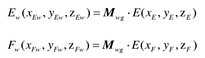
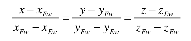
Through the coordinate transformation matrix MWG, the point E (Xe, ye, Ze) and point F (XF, YF, ZF) in the gear coordinate system SG are transformed into the gear hob coordinate system SW, respectively:
In the gear hob coordinate system SW, the normal equation of the gear tooth surface is expressed as:
Simultaneous formula, that is, the involute helicoid equation of gear hob is substituted into the normal equation of gear tooth surface( α, y, φ g) The unique parameter can be obtained by taking the parameter( ρ,θ) Represents the intersection coordinates of the normal of the gear tooth surface and the involute helical surface of the gear hob. The coordinates of the intersection can be recorded as point GW (XGW, ygw, zgw).