(1) Acceleration signal testing principle
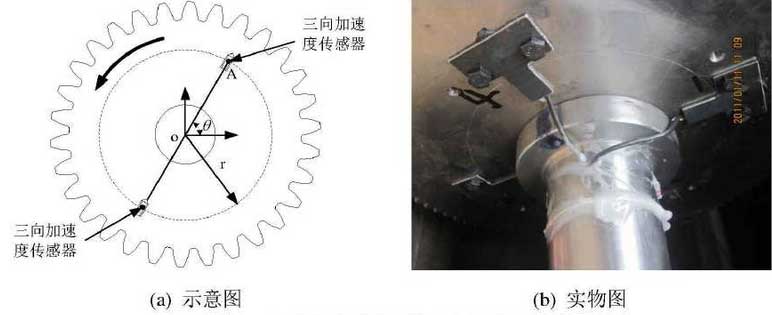
A three-way acceleration sensor is installed at 180 degrees intervals on the same circumference of the two-stage fixed-shaft gear drive test transposed gears 1 and 4 to test the vibration acceleration of the gear.The installation diagram and physical diagram of the acceleration sensor are shown in the figure.The installation position of acceleration sensor on gear 1 is 95mm from the axis and 69mm from the axis on gear 4.The acceleration signal line is guided out through the collector ring at each axle end and connected to the data acquisition and analysis system.
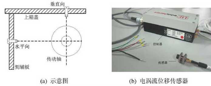
(2) Test principle of displacement signal
An eddy current displacement sensor is installed in the horizontal and vertical directions of the middle section of the drive shaft where gear 1 and gear 4 are located, respectively, as shown in Figure a, to measure the transverse vibration displacement of the drive shaft.The whole displacement sensor assembly consists of sensor, controller and signal wire as shown in Figure B.The distance between the front face of each sensor and the test surface is about 1mm under static conditions.The signal wire of the eddy current displacement sensor extends out to the controller through the wire hole reserved on the cover, and then connects to the data acquisition and analysis system.
(3) Principle of strain signal test
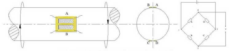
This test uses full-bridge wiring method to measure torsional shear strain of combined deformation of drive shaft. Full-bridge wiring method can eliminate the influence of bending, axial force and temperature changes, increase reading strain and improve test sensitivity. Full-bridge measuring method strain gauge sticker diagram and wiring diagram are shown in the figures.On the drive shaft between gear 2 and gear 3, two strain gauges with a resistance of 350Ohm are affixed to the symmetrical plane along the axis to test the torsional shear strain according to the full-bridge measuring method. The strain gauges of the drive shaft are affixed to the physical drawing as shown in the figure.The signal line of the strain gauge is connected to the dynamic Runs strain gauge through the collector ring, the strain bridge box and the output of the strain gauge to the data acquisition and analysis system.
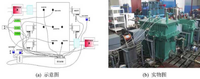
According to the test principle of acceleration, displacement and strain signals mentioned above, the schematic diagram and physical diagram of each sensor in the whole test system are shown in the figure.