1. Introduction
In the realm of modern manufacturing, gears play a crucial role in power transmission systems across various industries, such as automotive, aerospace, and machinery. The surface quality of gears significantly impacts their performance, including fatigue life, noise levels, and transmission efficiency. As industrial requirements for high – performance gears continue to grow, advanced surface finishing technologies are essential. Spindle – type roller polishing and finishing is a promising method for enhancing gear surface integrity. This article aims to comprehensively explore the particle behavior and processing characteristics in this machining process.
2. Background of Spindle – Type Roller Polishing and Finishing
2.1 Significance of Gear Surface Quality
High – quality gear surfaces are necessary to ensure smooth power transmission. Rough or damaged surfaces can lead to increased friction, wear, and noise during gear operation. For example, in automotive transmissions, poor – quality gear surfaces can reduce fuel efficiency and increase maintenance costs. In aerospace applications, where reliability is of utmost importance, surface flaws on gears can pose a serious safety risk. Table 1 summarizes the impacts of different surface qualities on gear performance.
| Surface Quality | Impact on Gear Performance |
|---|---|
| Rough surface | Higher friction, increased wear, more noise |
| Smooth surface | Lower friction, reduced wear, less noise |
| Damaged surface | Potential failure, decreased reliability |
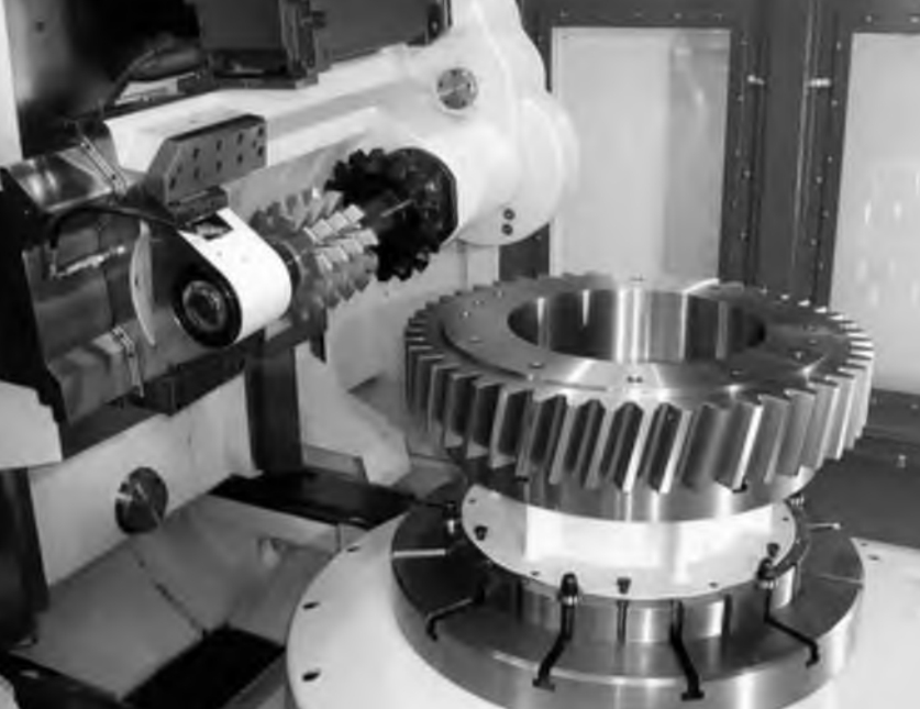
2.2 Overview of Spindle – Type Roller Polishing and Finishing
Spindle – type roller polishing and finishing is a machining process that utilizes the relative motion and interaction between particles and gears to improve the gear surface. It consists of components like a roller, particles, a workpiece (gear), and a fixture. During processing, the fixture and the roller rotate simultaneously, causing the particles to move relative to the gear and exert forces on its surface, which can remove burrs, reduce surface roughness, and improve the surface finish. Figure 1 shows the schematic diagram of the spindle – type roller polishing and finishing setup.
[Insert Figure 1: Schematic diagram of spindle – type roller polishing and finishing setup. The figure should clearly show the roller, particles, gear, and fixture. The roller is rotating, and the particles are in contact with the gear surface.]
3. Research on Particle Behavior in Spindle – Type Roller Polishing and Finishing
3.1 Particle Motion in the Vicinity of the Gear
When the spindle – type roller polishing and finishing process is in operation, the particles’ motion near the gear is complex. Due to the rotation of the roller and the gear, the particles are affected by multiple forces, including gravitational force, centrifugal force, and the frictional force between particles and the gear surface.
In the area around the gear, the particles’ motion can be divided into different patterns. In the region close to the gear teeth, the particles are more likely to be trapped in the tooth gaps, and their motion is restricted by the tooth profile. As shown in Figure 2, some particles move along the tooth surface, while others may bounce between different teeth. Table 2 categorizes the different particle motion patterns near the gear.
| Motion Pattern | Description |
|---|---|
| Trapped in tooth gaps | Particles are caught between adjacent teeth and move along the tooth – gap space |
| Moving along tooth surface | Particles slide or roll on the tooth surface |
| Bouncing between teeth | Particles collide with teeth and change their direction of motion |
| [Insert Figure 2: Particle motion near the gear teeth. The figure should show particles in different positions around the gear teeth, with arrows indicating their direction of motion.] |
3.2 Contact Particle Motion on the Tooth Surface
The motion of particles in contact with the tooth surface is also crucial for understanding the machining mechanism. These particles can be divided into three stages during their interaction with the tooth surface: the filling stage, the stable – filling stage, and the outflow stage.
During the filling stage, as the gear rotates, particles start to enter the tooth gaps from the gear’s upper end face and the tooth tips. At this time, the particles’ velocity is relatively high, and they move vertically downward. As the particles continue to flow in, the tooth gaps gradually fill up, and the particle velocity begins to decrease.
In the stable – filling stage, when the tooth gaps are filled with particles, the particles’ motion direction changes. They start to move upward along the tooth surface due to the impact and extrusion of the gear. In this stage, the number of particles in contact with the tooth surface remains relatively constant, and their velocity is relatively low.
Finally, in the outflow stage, as the tooth gaps move out of the main impact area between the particles and the gear, the particles are affected by the gear’s centrifugal force and gravity and flow out of the tooth gaps. Figure 3 shows the velocity vector diagrams of particles in different stages of contact with the tooth surface.
[Insert Figure 3: Velocity vector diagrams of particles in different stages of contact with the tooth surface. There should be three sub – figures, each showing the velocity vectors of particles in the filling stage, stable – filling stage, and outflow stage respectively.]
4. Factors Affecting Particle – Gear Interaction
4.1 Influence of Gear Embedding Depth
The gear embedding depth refers to the distance from the gear’s upper end face to the particle upper – interface when the system is at rest. A change in the gear embedding depth can have a significant impact on the interaction between particles and the gear.
When the gear embedding depth increases, more particles can come into contact with the gear surface. This leads to an increase in the contact force between the particles and the gear teeth. Table 3 shows the relationship between gear embedding depth and contact force. When the embedding depth increases by 75% (from 80 mm to 140 mm), the tooth – surface contact force increases by 76%.
| Gear Embedding Depth (mm) | Tooth – Surface Contact Force Change |
|---|---|
| 80 | – |
| 110 | Contact force increases |
| 140 | 76% increase compared to 80 mm |
In addition, increasing the gear embedding depth can also reduce the processing difference along the gear’s axial direction. As shown in Figure 4, when the embedding depth is increased from 80 mm to 140 mm, the roughness reduction rates of the upper and lower tooth surfaces along the axial direction change from 17% and 36% to 62% and 55% respectively.
[Insert Figure 4: Influence of gear embedding depth on the roughness reduction rate along the gear’s axial direction. The x – axis represents the embedding depth, and the y – axis represents the roughness reduction rate. There should be two curves, one for the upper tooth surface and one for the lower tooth surface.]
4.2 Influence of Gear and Roller Rotation Speeds
The rotation speeds of the gear and the roller also play important roles in the particle – gear interaction. A higher rotation speed can increase the relative motion speed between the particles and the gear surface.
When the gear and roller rotation speeds increase by 150% (for example, from 12 r/min to 30 r/min), the relative motion speed of the particles in contact with the tooth surface increases by 148%. Table 4 shows the change in the relative motion speed of particles with different rotation speeds.
| Gear and Roller Rotation Speed (r/min) | Relative Motion Speed of Particles Change |
|---|---|
| 12 | – |
| 21 | Relative motion speed increases |
| 30 | 148% increase compared to 12 r/min |
However, the impact of rotation speed on the contact force between particles and the gear is relatively small. When the rotation speed increases from 12 r/min to 30 r/min, the tooth – surface contact force only increases by 18%.
5. 不均匀性 in Spindle – Type Roller Polishing and Finishing
5.1 Uneven Force on the Tooth Surface
In the spindle – type roller polishing and finishing process, the forces on different parts of the gear tooth surface are uneven. The upper tooth surface generally receives a greater contact force than the lower tooth surface. In the simulation of five working conditions, the average normal contact force on the upper tooth surface is 1.52 – 1.88 times that on the lower tooth surface.
This is mainly due to the semi – enclosed structure of the tooth gaps. When there are more particles in the tooth gaps, the impact force of the particle group gradually dissipates through friction with the tooth surface and among the particles themselves. As a result, the tooth surface closer to the bottom of the tooth gap (tooth root) receives less force, leading to an uneven force distribution from the tooth root to the tooth tip. Table 5 shows the comparison of contact forces on the upper and lower tooth surfaces under different conditions.
| Working Condition | Upper Tooth Surface Contact Force (N) | Lower Tooth Surface Contact Force (N) | Ratio (Upper / Lower) |
|---|---|---|---|
| Condition 1 | – | – | 1.52 – 1.88 |
| Condition 2 | – | – | 1.52 – 1.88 |
| … | … | … | … |
5.2 Uneven Relative Motion Speed of Particles
The relative motion speed of particles on the upper and lower tooth surfaces is also uneven. The average relative motion speed of particles on the upper tooth surface is 1.35 – 1.45 times that on the lower tooth surface. This is because the structure of the tooth gaps affects the particle motion. In the tooth – gap area, the particles’ motion is restricted, and the upper tooth surface provides more space for the particles to move freely, resulting in a higher relative motion speed. Figure 5 shows the distribution of particle relative motion speeds on the upper and lower tooth surfaces.
[Insert Figure 5: Distribution of particle relative motion speeds on the upper and lower tooth surfaces. The figure can be a bar chart or a line chart comparing the relative motion speeds of particles on the two surfaces.]
6. Experimental Verification of Simulation Results
6.1 Experimental Setup
To verify the simulation results, an experimental platform for spindle – type roller polishing and finishing gear strain testing was built based on the X1400 swirl vertical free – abrasive – tool polishing machine. The platform consists of components such as the DH5903N solid – state dynamic signal testing and analysis system, strain gauges, motors, rollers, fixtures, workpieces (gears), and a computer.
Resistive strain gauges (BX120 – 10AA) were pasted on the tooth surface, upper end face, and lower end face of the gear. The embedding depth and rotation speed settings in the experiment were consistent with those in the simulation. The sampling frequency was set to 10 kHz, and each working condition was tested twice. Figure 6 shows the experimental platform for spindle – type roller polishing and finishing gear strain testing.
[Insert Figure 6: Experimental platform for spindle – type roller polishing and finishing gear strain testing. The figure should clearly show all the components of the platform, with the gear, strain gauges, and other parts clearly visible.]
6.2 Experimental Results and Comparison with Simulation
The experimental results showed good agreement with the simulation results. The stress on the tooth surface changed periodically with the rotation of the gear, which was consistent with the discrete – element simulation analysis. In addition, the stress on the lower end face of the gear was significantly greater than that on the upper end face, indicating uneven processing on the upper and lower end faces, which also matched the simulation conclusion.
By comparing the stress and normal contact force under different rotation speeds and embedding depths, it was found that the depth was the main factor affecting the particle – gear interaction force. When the embedding depth increased by 75%, the stress at three positions on the gear increased by 59%, 35%, and 43% respectively, and the normal contact force increased by 32%, 40%, and 34% respectively. Table 6 shows the comparison of experimental and simulation results for stress and normal contact force changes.
| Parameter Change | Experimental Stress Change | Simulation Normal Contact Force Change |
|---|---|---|
| 75% increase in embedding depth | 59%, 35%, 43% increase at three positions | 32%, 40%, 34% increase at three positions |
| 150% increase in rotation speed | 17%, 28%, 17% increase at three positions | 14%, 26%, 5% increase at three positions |
7. Application and Future Development of Spindle – Type Roller Polishing and Finishing
7.1 Current Applications
Spindle – type roller polishing and finishing has been widely applied in various industries. In the automotive industry, it is used to improve the surface quality of gears in transmissions, reducing noise and improving fuel efficiency. In the aerospace industry, it helps to enhance the reliability of gears in aircraft engines and landing gear systems. In the machinery manufacturing industry, it can improve the performance and service life of gears in various types of equipment. Table 7 lists some specific applications in different industries.
| Industry | Application of Spindle – Type Roller Polishing and Finishing |
|---|---|
| Automotive | Improving gear surface quality in transmissions |
| Aerospace | Enhancing gear reliability in engines and landing gear |
| Machinery Manufacturing | Improving gear performance and service life in equipment |
7.2 Future Development Trends
In the future, the development of spindle – type roller polishing and finishing is expected to focus on the following aspects. Firstly, further research on the particle – gear interaction mechanism is needed to optimize the processing parameters more accurately. Secondly, the combination of this technology with other advanced manufacturing technologies, such as 3D printing, can expand its application scope, especially for non – standard and complex – shaped gear processing. Thirdly, the development of intelligent control systems for spindle – type roller polishing and finishing can improve the processing efficiency and product quality. Figure 7 shows the potential development directions of spindle – type roller polishing and finishing.
[Insert Figure 7: Potential development directions of spindle – type roller polishing and finishing. The figure can be a mind – map – like diagram showing the three main development directions: mechanism research, combination with other technologies, and intelligent control.]
8. Conclusion
Spindle – type roller polishing and finishing is an effective method for improving the surface quality of straight – cylindrical gears. Through discrete – element simulation and experimental verification, this article has comprehensively explored the particle behavior and processing characteristics in this process.
The motion of particles near the gear and on the tooth surface is complex, and it can be divided into different stages. The gear embedding depth and rotation speeds of the gear and roller have significant impacts on the contact force and relative motion speed between particles and the gear. There are uneven forces and relative motion speeds on the gear tooth surface, and increasing the gear embedding depth can reduce the processing difference along the axial direction.
The experimental results verify the effectiveness of the simulation, which provides a theoretical basis for optimizing the processing parameters of spindle – type roller polishing and finishing. In the future, with the continuous development of technology, spindle – type roller polishing and finishing is expected to play an even more important role in the manufacturing industry.