
With the increasing trend of high efficiency and high precision in gear processing technology,Traditional manual chamfering and manual input of numerical control machiningCode is increasingly difficult to meet the requirements of modern production and processing, and automation isEdge technology has also gradually entered the public’s field of vision.Automated chamfering technologyThe operator only needs to simply input the parameters of the gear (such as the spiralangle, large end module, number of teeth of small gear, number of teeth of large gear, tooth width,tooth angle, nominal radius of the cutter head, length of the exposed cutting edge, cutting tool angle,chamfer length and tooth thickness adjustment coefficient, etc.), the system will automatically calculateOther parameters required for chamfering technology, and then automatically generate NC codes for chamfering on the machine tool for automated chamfering.This technology does not requireThe operator must have systematic expertise, as long as they simply inputThe programming task can be completed by entering the corresponding parameters without the need for specializedtechnical training, thereby reducing production costs.In terms of secondary development of CNC systems, for the Fagor CNC system,There are very few documents on secondary development.For strong scraping teethSecond-order development of Siemens 840D, promoting the machining of scraping teeth;Secondary development based on Siemens 840D to meet the requirements of gear grindingCompensation control software developed based on the Siemens 840D CNC system human-machine interface software;Xue Gang proposed a secondary development based on the Fanuc C language actuatorMethod [9];Chi Wenhui used the FANUC CNC system’s built-inFANUC PICTURE development software for human-machine interface development, improvingthe operability of the machine tool [10];Sun Kexing et al. aimed at the current CNC machine toolDifficulties in information exchange and lack of transparency in the production and management processes of bedsMinghe has low operational efficiency and other issues. Design a set of solutions based on EthernetDNC system of FANUC CNC machine tools;Ding Guolong et al.Turbine machining, based on the HNC-848 CNC system in Central Chinadevelopment, providing a practical toolkit for the secondary development of domestic CNC systems.Method: Based on the research of Wings E, Toquica J S and others abroadLinuxCNC has undergone secondary development on the numerical control system, resulting in improved performance.Better numerical control system to cope with different processing situations.Combining the above-mentioned secondary development research, FAGORCNC8070-OL is a secondary development system object based on FAGORThe secondary development platform FGUIM software provided by the 8070-OL CNC systemusing VB.net and C++ mixed programming technology, developed aThe open-type numerical control system can customize the special needs of users more conveniently,Realize automated chamfering technology.
1 Solution for chamfering trajectory of spiral bevel gear
1.1 Solution of the equation of the tooth top edge
To develop software for chamfering the tooth crest of spiral bevel gears, firstDemand to solve the parameterized equation of chamfering trajectory of spiral bevel gear, which is convenient forWrite code programs for software secondary development.
1.2 Solution of tool trajectory equation
The end face involute profile equation and tooth tip of the helical bevel gear are combinedSolve the equation of the circle to obtain the angle of the involute at point
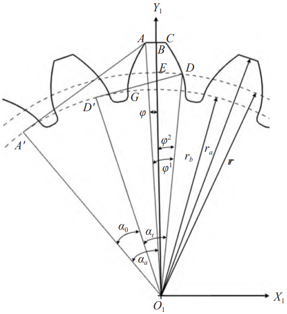
Figure 1 Schematic diagram of the tooth crest ridge of spiral bevel gear
As shown in Figure 2, the angle from the starting point of the base circle
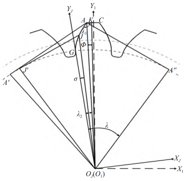
Figure 2 Schematic diagram of points J and K on the involute and addendum circle
As shown in Figure 3,∆JAKIn , we can obtain:
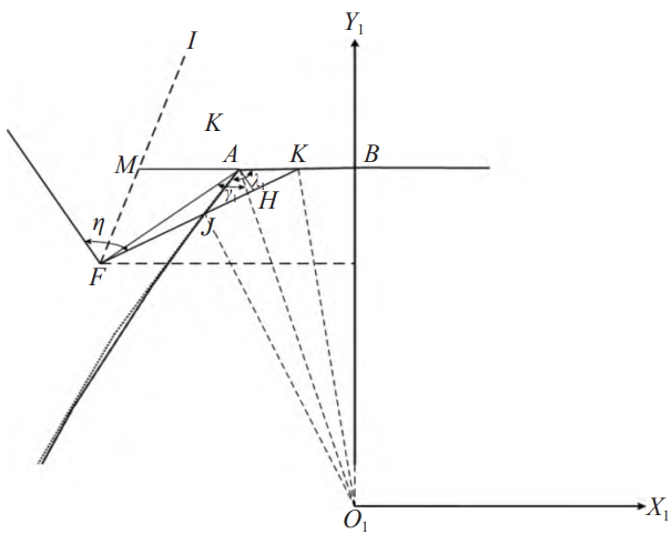
Figure 3 Schematic diagram of the tool trajectory point F and the point M on the tool vector line
2 Automatic chamfering of spiral bevel gear tooth tip
2.1 Basic process of CNC8070-OL secondary development
Based on the FGUIM software developed by FAGOR, firstlyTo develop a third-party software independently, that is, to develop a self-developing software for spiral bevel gears,Automated chamfering software for tooth top.Firstly, use VB.net to designhuman-computer interface;then use C++ in the development environment of VS 2015Write back-end programs and package them into multiple COM components forVB.net direct reference, automatic generation of NC code for processingFinally, through the FGUIM software and the CNC8070-OL digital control system,The interconnection between the control systems enables third-party software to be embedded into the CNC system.In order to embed the software into the numerical control system, it is necessary to copy the path of the software, such as: “E:\VS2015\VB\RJJM\RJJM\obj\Debug\RJJM.exe” (note that it must be copied to a folder with a.exe extensionand then copy it. Double-click to open the FGUIM software.Select the required “automatic” or “manual” in the “component”Mode, click the “S” button in the menu bar, and aVBscrip script, in which we need to enter code to ensureThe smooth connection between third-party software and CNC8070-OL is shown in Figure 4.After completing the connection, in order to make the third-party software more concise and clear,Displayed on the interface of the numerical control system, it needs to be set in the FGUIM software.Select the “ED” button in the menu bar and click it to display the settings interfaceOn the screen, you can set the location, icon name, and iconConnection identifiers with CNC8070-OL, etc., as shown in Figure 5.
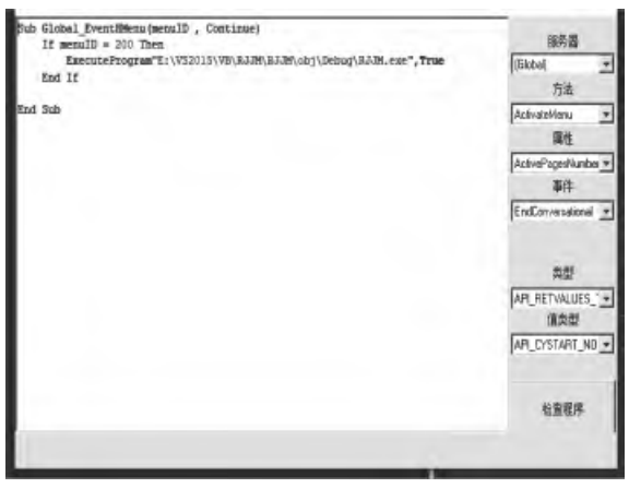
Figure 4: Smooth connection between third-party software and CNC8070-OL
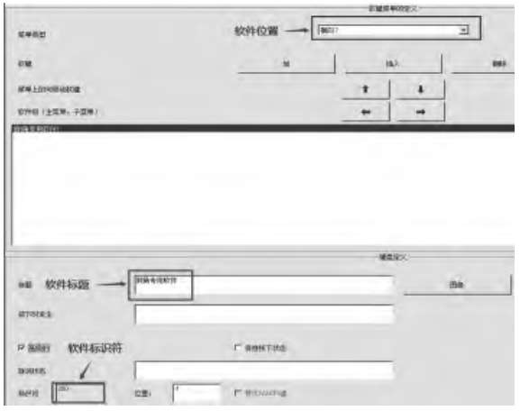
Figure 5 Connection prompt
2.2 Automatic chamfering of tooth tip for spiral bevel gear
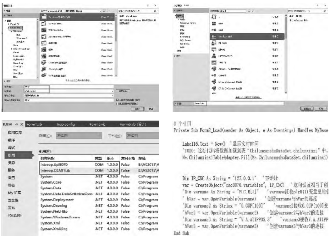
Main development process flowThe process is shown in Figure 6.(1) Create a new Visual Basic form application, selectEnter the path and file name to create a project file.(2) Click Form1.vb to jump to the first form we want to develop.An interface where we can select the tools we need in the toolbox on the leftControl, just click and drag it to the development interface, and you can change the size freely.When you want to add a new development interface, right-click the solution assetAdd the previously set name file RJJM in the source managerSelect a new Windows form, select a path, and enter a form name.If you want to create more development interfaces, follow this method.(3) In addition to the development of the interface, the development of software also requiresTo have the function of automatic chamfering, it needs to be written in C++The background logic program of the encapsulated into multiple COM components.Left double clickClick “My Project” → “Reference” in Solution ExplorerUse ” → ” COM type library” to find the required COM group件→ “ 确定”。After the reference is completed, it is necessary to program VB again.Code, making the functions of COM components available to VB.net.(4) After successfully installing the CNCFAGOR.exe simulation software,Connect the API8070.SERVER library interface according to the above method to achieveCommunicate and exchange data with the numerical control kernel.
2.3 Main functions of the automatic chamfering software for spiral bevel gear tooth topsThe module
According to the processing requirements of chamfering the tooth tip, it can be known that the software can be divided intoThe following modules are formed: gear parameters, process parameters, parameter calculation, productionThere are 7 modules, such as program, program management, alarm and status.Figure 7-8.
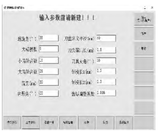
Figure 7 Main functional module interface
Based on the development provided by the CNC8070-OL CNC system to users,It can be known from the interface that the software for chamfering the tooth top of the spiral bevel gear adoptsMicrsoft Access 2010 database as data support, canGood communication and transfer of information between the ground and the numerical control system.
2.4 Automatic generation of CNC machining programs
Automatic generation of CNC machining program code is the key to automaticThe main functional module of the chamfering software for the tooth top is the entire softwarethe most important thing.In the above 2.2 (3), it is mentioned that “C++The multiple COM components encapsulated by the background logic program writtenIt is the method to achieve this function.
2.5 Simulation
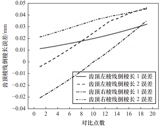
Left and right edges generated by the software for chamfering the tooth crest of spiral bevel gearsThe program is imported into the VERICUT simulation software, and the machine tool,Simulation is performed after blanking and cutting tools, and the simulation results are shown in Figure 10.From Figure 10It can be seen that the chamfered surface is smooth and uniform, and the size of the chamfer at both ends is relativelyGood consistency.The chamfered line calculated theoretically and the chamfered line simulated in practice are dividedDon’t evenly take 20 points and import them into Origin to draw a line chart, as shown inFigure 11.The figure shows that the length error after cutting by the tool does not exceedIt is 0.045 mm, which meets the chamfering error requirement.

3 Conclusion
(1) Introduced the tooth flank profile equation and cutting tool of spiral bevel gearThe solution of the trajectory equation provides a theoretical basis for secondary development.(2) Introduced the FGUIM based on the FAGOR systemSoftware, using mixed programming of C++ and VB.net, for FAGORSpecific process steps for secondary development of CNC8070-OL CNC systemEmbedding the spiral in the FAGOR CNC8070-OL CNC systemThe software for chamfering the tooth tip of bevel gears makes the operation easier and more efficient.Increase efficiency and reduce operational difficulty, for the promotion of chamfering of spiral bevel gearsProcessing has positive significance for further research on the tooth crest of spiral bevel gearsChamfering provides conditions.