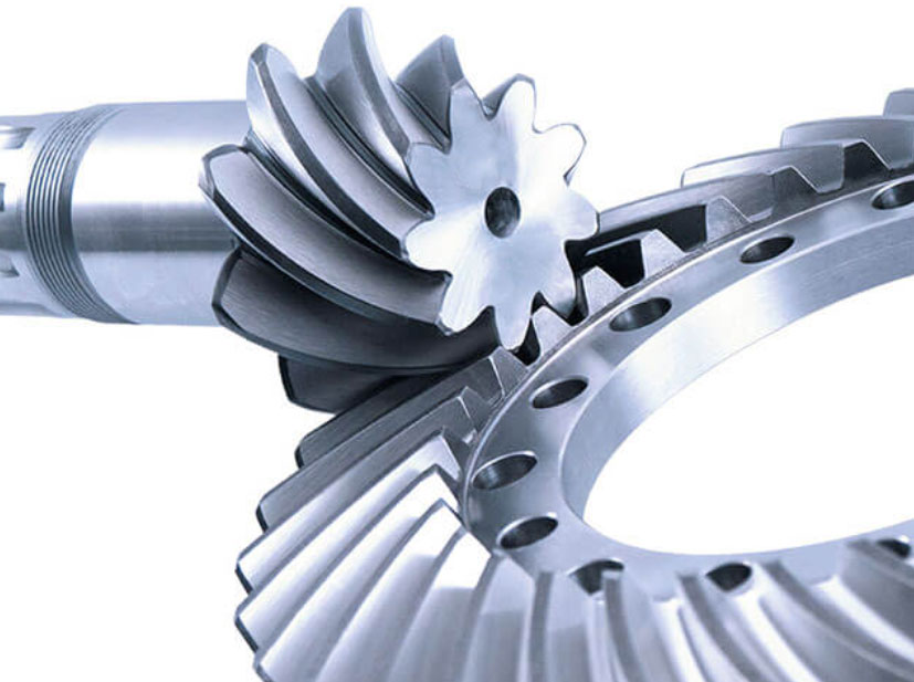
Spiral bevel gears have complex tooth geometry, making their design and tooth contact analysis essential for optimal performance and durability. A comprehensive review of spiral bevel gear geometry and tooth contact analysis involves understanding the gear geometry, tooth contact pattern, and various methods used to assess the gear’s performance. Here’s an overview of these aspects:
1. Gear Geometry:
- Spiral bevel gears have curved teeth that follow a helical path around the gear axis. The tooth geometry is defined by parameters such as the module, pitch diameter, helix angle, face width, and the number of teeth. The gear geometry is crucial for smooth tooth engagement and efficient power transmission.
2. Tooth Contact Pattern:
- The tooth contact pattern refers to the area of contact between the mating teeth during meshing. Achieving the proper tooth contact pattern is essential for load distribution and preventing premature wear. The goal is to achieve a well-centered and uniform contact pattern across the gear face width.
3. Tooth Contact Analysis Methods:
a. Graphical Method:
- The graphical method involves physically applying a special marking compound to the gear teeth and then rotating the gears to observe the resulting contact pattern. This traditional method provides a qualitative understanding of the contact pattern but lacks precise measurements.
b. Coordinate Measuring Machines (CMM):
- CMMs can be used to measure the tooth contact pattern accurately. By scanning the contact area, the gear designer can obtain quantitative data to assess the gear’s performance and identify any deviations from the desired contact pattern.
c. Finite Element Analysis (FEA):
- FEA is a computational method used to analyze the tooth contact pattern and assess the gear’s performance under various operating conditions. FEA can provide detailed stress and deformation analysis, allowing designers to optimize the gear geometry and tooth contact pattern.
d. Computer-Aided Design (CAD) Simulation:
- CAD software can simulate the meshing of spiral bevel gears and provide insights into the contact pattern and potential issues. This method helps evaluate different design variations before physical prototyping.
e. Tooth Contact Pattern Software:
- Specialized tooth contact pattern software is available that can analyze and optimize the contact pattern based on the gear’s specific design parameters.
4. Tooth Contact Pattern Optimization:
- Tooth contact pattern optimization involves adjusting the gear parameters to achieve the desired contact pattern characteristics. The goal is to maximize contact area, minimize edge loading, and ensure uniform load distribution across the gear teeth.
5. Influence of Manufacturing Tolerances:
- Manufacturing tolerances can affect the actual tooth contact pattern in comparison to the designed pattern. Analyzing the influence of manufacturing tolerances helps ensure the gears’ performance matches the intended design.
A comprehensive review of spiral bevel gear geometry and tooth contact analysis involves a combination of experimental testing, analytical methods, and computer simulations to understand and optimize the gear’s performance. The goal is to achieve smooth tooth engagement, minimize noise and vibration, and ensure the gears’ reliable operation under various load conditions.
