This article focuses on the dynamic characteristics of the spindle system of a spiral bevel gear milling machine and its matching with processing technology. It begins with an introduction to the research background and significance, followed by a detailed analysis of the spindle system’s dynamic modeling and response. The cutting force, a crucial factor in the milling process, is modeled and analyzed under different process parameters. Through simulations and experiments, the optimal process parameters are determined and verified for their matching effect with the spindle system. This research provides a more efficient way to select process parameters and fully utilizes the performance of the milling machine.
1. Introduction
1.1 Research Background and Significance
In modern manufacturing, machine tools play a vital role. The dynamic performance of machine tools directly affects the quality of workpieces and machining efficiency. The spindle system, as a key component in contact with the workpiece, has a significant impact on the vibration characteristics of the machine tool. Understanding and controlling the vibration of the spindle system is crucial for improving machining accuracy and efficiency. In the case of spiral bevel gear milling machines, the dynamic characteristics of the spindle system and the selection of process parameters are particularly important as they affect the tooth surface quality and machining efficiency of the gears.
1.2 Research Status at Home and Abroad
- Dynamic Modeling Technology: Various methods such as concentrated parameter method, transfer matrix method, and finite element method have been used for spindle dynamic modeling. Each method has its own advantages and limitations. For example, the concentrated parameter model is simple but may not accurately simulate complex structures. The transfer matrix method is efficient but may have reduced accuracy for high-order modes. The finite element method is widely used and can provide accurate results for static and dynamic analysis of the spindle system.
- Research on Excitation Force: Studies on excitation forces have included using artificial excitation during machine shutdown and exploring new excitation methods such as electromagnetic exciters and piezoelectric sensors. The use of cutting force as an excitation source has also been investigated, but research on the excitation force during spiral bevel gear milling is relatively limited.
- Research on Process Matching: Optimization of process parameters has been carried out through various algorithms such as artificial neural networks, simulated annealing algorithms, and genetic algorithms. Some studies have also focused on experimental or simulation methods to select appropriate process parameters. However, research on the process parameter optimization for spiral bevel gear milling machines is scarce.
1.3 Research Contents and Ideas of This Topic
This research aims to establish a dynamic numerical model of the spindle system of a spiral bevel gear milling machine based on finite element dynamics theory and Timoshenko beam theory. The harmonic and transient responses of the system are analyzed. A theoretical cutting force model for machining the pinion is established, and the influence of process parameters on the cutting force is analyzed. Through simulations and experiments, the optimal process parameters are determined and verified for their matching effect with the spindle system.
2. Dynamic Modeling and Analysis of the Spindle System
2.1 Basic Principles of Rotor Dynamic Equation Construction
The dynamic model of the spindle system can be established through theoretical modeling, experimental modeling, or a combination of both. In this research, the finite element method is used. The energy principle is applied to obtain the dynamic equation of the unit body. The equations for kinetic energy, potential energy, and work done by non-conservative forces are derived. The unit mass matrix, damping matrix, and stiffness matrix are obtained, and the system’s dynamic balance equation is assembled.
2.2 Dynamic Modeling of the Spindle System Based on Beam Elements
The spindle system of the milling machine includes components such as the shaft, bearings, and milling cutter head. To simplify the calculation, the spindle system is appropriately simplified. The Timoshenko beam model, which considers shear deformation, is used for simulation. The system is discretized into multiple elements, and the mass and stiffness matrices of each element are analyzed. The total mass matrix and stiffness matrix of the system are assembled, considering the coupling effect of the bearings.
2.3 Establishment of the System Motion Differential Equation
- Unit Mass Matrix and Stiffness Matrix: The Timoshenko beam model is used to calculate the unit mass and stiffness matrices. The expressions for the mass matrix and stiffness matrix elements are derived, considering the degrees of freedom of each node.
- System Total Assembly Mass Matrix and Stiffness Matrix: The unit mass and stiffness matrices are assembled to obtain the total mass matrix and stiffness matrix of the system. The coupling effect of the bearings is considered by adding the bearing stiffness matrices at the appropriate nodes.
- Spindle System Motion Differential Equation: The motion differential equation of the spindle system is obtained, which includes the total mass matrix, damping matrix, stiffness matrix, and external force vector. The equation for the system’s free vibration is also derived.
2.4 Natural Frequencies and Modal Shapes
The natural frequencies and modal shapes of the spindle system are calculated using Matlab and finite element software. The results show that the calculated natural frequencies by both methods are generally consistent, validating the effectiveness of the simplified model and the calculation method. The differences in the results may be due to model assumptions, numerical calculation accuracy, boundary condition settings, and program implementation.
2.5 Harmonic Response Analysis of the Spindle System
- Basic Theory of Harmonic Response Analysis: Harmonic response analysis is used to study the system’s response to periodic excitation. The dynamic equation for harmonic response analysis is derived, and the expressions for displacement, velocity, and acceleration are obtained. The inertia force, damping force, and deformation force caused by the excitation are analyzed.
- Harmonic Response Analysis of the Spindle System Based on Matlab: The spindle system’s harmonic response is analyzed using the mode superposition method in Matlab. The results show that the system has a resonance phenomenon at a certain frequency, and the displacement in different directions shows different characteristics under external excitation.
2.6 Transient Dynamic Analysis
Transient dynamic analysis is carried out to study the system’s response to sudden and periodic loads during the machining process. The Newmark method is used to calculate the displacement of the spindle system in different directions under impact loads. The results show that the bearing has a buffering effect on the impact load, and different process parameters affect the impact load on the system.
2.7 Summary of This Chapter
This chapter establishes a dynamic model of the spindle system using the Timoshenko beam theory. The natural frequencies, modal shapes, harmonic responses, and transient responses of the system are analyzed. The results validate the accuracy of the model and provide a theoretical basis for the selection of process parameters.
3. Analysis of the Milling Cutting Excitation Force
3.1 Dynamic Force Analysis of Spiral Bevel Gear Milling
In the milling process, the spindle system is affected by various excitation forces, and the cutting force is the most important one. The appropriate selection of process parameters is crucial for reducing the cutting force and improving the machining performance.
3.2 Theoretical Milling Cutting Force Model
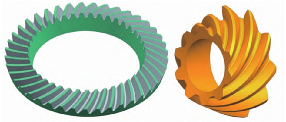
- Analysis of Spiral Bevel Gear Milling: The cutting process of the spiral bevel gear using the generating method is analyzed. The motion relationship between the cutter head and the gear blank is described, and the basic structure of the cutter head is introduced.
- Oblique Cutting Model: The oblique cutting model is established based on the mechanics of cutting. The coordinate systems for oblique cutting are defined, and the relationships between different coordinate systems are derived. The forces acting on the cutting tool and the chip are analyzed.
- Equation of the Cutter Head Generating Surface for Machining the Pinion: The equation of the cutter head generating surface for machining the pinion is derived, and the unit normal vector on the cutting edge is obtained.
- Calculation of the Cutter Head Cutting Force Components: The cutting force components in different directions are calculated based on the oblique cutting theory and the equation of the cutter head generating surface.
3.3 Influence Analysis of Process Parameters Based on the Theoretical Cutting Force Model
- Influence of Feed Rate on Cutting Force: The influence of feed rate on the cutting force is analyzed using the theoretical cutting force model. The results show that the cutting force increases with the increase of feed rate, and the Y direction has the largest cutting force.
- Influence of Spindle Speed on Feed Rate: The influence of spindle speed on the feed rate is analyzed. The results show that the cutting force increases with the increase of spindle speed, and the Y direction still has the largest cutting force.
3.4 Finite Element Simulation of Spiral Bevel Gear Milling Cutting Force Based on AdvantEdge FEM
- Simulation Process of AdvantEdge FEM Software: The simulation process of the AdvantEdge FEM software is introduced, including the selection of simulation types, setting of simulation parameters, calculation of simulation, and post-processing of results.
- Establishment of the Finite Element Simulation Model: The finite element simulation model is established by simplifying the models of the cutter head and the gear blank. The material properties and relative positions of the cutter head and the gear blank are set.
- Simulation Results of Milling Cutting Force: The simulation results of the milling cutting force under different process parameters are analyzed. The results show that the cutting force increases with the increase of feed rate and spindle speed, and the Y direction has the largest cutting force.
3.5 Frequency Component Analysis of the Simulation Cutting Force
- Influence of Feed Rate on the Frequency Component of Cutting Force: The influence of feed rate on the frequency component of cutting force is analyzed. The results show that the frequency distribution of the cutting force is mainly concentrated in the low-frequency region, and the cutting force amplitude increases and tends to shift to high frequencies when the feed rate is 0.4mm.
- Influence of Spindle Speed on the Frequency Component of Cutting Force: The influence of spindle speed on the frequency component of cutting force is analyzed. The results show that the frequency distribution of the cutting force is mainly concentrated in the low-frequency region, and the cutting force amplitude changes with the increase of spindle speed.
3.6 Summary of This Chapter
This chapter analyzes the cutting force as the main excitation source in the milling process. A theoretical cutting force model is established, and the influence of process parameters on the cutting force is analyzed. The cutting force is simulated using the AdvantEdge FEM software, and the frequency components of the cutting force are analyzed. The results provide a basis for the optimization of process parameters.
4. Dynamic Characteristics Analysis and Verification of Process Matching Effect
4.1 Transient Response Analysis Based on Theoretical Cutting Force
Based on the calculated results of the theoretical cutting force, the transient response of the system is analyzed. Four sets of cutting force amplitudes are selected and substituted into the finite element model to study the system’s response. The results show that when the feed rate is 0.3mm and the spindle speed is 120rpm, the system has the smallest vibration amplitude and the shortest recovery time.
4.2 Verification by Milling Cutting Experiments
- Introduction to the Rotary Dynamometer: The Kistler rotary dynamometer is introduced, which can measure the cutting force during milling. The installation and working principle of the dynamometer are described.
- Milling Cutting Force Experiments: Milling cutting force experiments are carried out using a YKH2235 CNC spiral bevel gear milling machine. Two sets of process parameters are selected for comparison, and the cutting force data in different directions are measured and analyzed. The results show that the measured cutting force is consistent with the theoretical and simulation results, and the Y direction has the largest cutting force.
- Milling Cutting Vibration Experiments: The vibration signals at the spindle end during the milling process are collected. The results show that the vibration amplitude increases with the increase of feed rate, and when the feed rate is 0.3mm and the spindle speed is 120rpm, the spindle system has a smaller vibration amplitude.
4.3 Process Matching
- Frequency Analysis of Milling Cutting Force: The frequency components of the cutting force collected in the experiments are analyzed. The results show that the cutting force frequencies of the two process parameters are mainly concentrated in the low-frequency region, and the first process parameter is more suitable for the spindle system as it has a smaller vibration amplitude.
- Response Analysis Based on Milling Excitation Force: The response of the spindle system to the cutting force in different directions is analyzed. The results show that the system is in a stable milling state under the selected process parameters, and the Y direction is the most sensitive to the cutting force.
- Process Optimization Based on Milling Experiments: The process parameters are optimized based on the experimental results. The feed speed is adjusted to keep the cutting force constant, reducing the milling time and the impact load on the spindle system. The bearing stiffness is also adjusted to change the sensitivity direction of the spindle system to the cutting force.
4.4 Summary of This Chapter
This chapter verifies the matching effect of the process parameters with the spindle system through transient response analysis and milling experiments. The optimal process parameters are determined, and the frequency components and sensitivity of the cutting force are analyzed. The process parameters are optimized to improve the machining efficiency and quality.
5. Summary and Outlook
5.1 Summary of the Full Text
This article has established a dynamic model of the spindle system of a spiral bevel gear…
6. The Impact of Spindle System Dynamic Characteristics on Gear Machining Quality
6.1 Gear Tooth Surface Quality
The dynamic characteristics of the spindle system have a direct impact on the tooth surface quality of the gears. During the milling process, vibrations in the spindle system can cause irregularities on the tooth surface. For example, if there is resonance in the spindle system at a certain frequency, it can lead to chatter marks on the tooth surface, reducing the surface finish and accuracy of the gear. The optimal process parameters determined in this research help to minimize these vibrations and thus improve the tooth surface quality.
| Process Parameter | Impact on Tooth Surface Quality |
|---|---|
| Feed Rate | A proper feed rate can ensure a smooth cutting process and avoid excessive cutting forces that may damage the tooth surface. |
| Spindle Speed | The correct spindle speed can reduce vibrations and ensure the accuracy of the gear tooth profile. |
6.2 Gear Machining Accuracy
Accurate machining of gears is crucial for their proper functioning in mechanical systems. The spindle system’s dynamic characteristics affect the positioning accuracy of the cutter head during the milling process. If the spindle system has poor dynamic stability, it can lead to errors in the gear tooth profile and pitch. The research on the matching of process parameters with the spindle system’s dynamic characteristics helps to improve the machining accuracy of gears.
| Dynamic Characteristic | Impact on Machining Accuracy |
|---|---|
| Natural Frequencies | Avoiding excitation frequencies close to the natural frequencies of the spindle system can prevent resonance and ensure accurate machining. |
| Modal Shapes | Understanding the modal shapes helps in predicting the vibration patterns and taking measures to correct any inaccuracies in the gear machining process. |
7. The Role of Simulation and Experiment in This Research
7.1 Simulation Studies
Simulation plays a crucial role in this research. The finite element simulations of the spindle system’s dynamic characteristics and the cutting force allow for a detailed analysis of the system’s behavior under different conditions. The AdvantEdge FEM software used for cutting force simulation provides valuable insights into the influence of process parameters on the cutting force. Through simulations, it is possible to predict the system’s response and optimize the process parameters without the need for extensive and costly experiments initially.
| Simulation Software | Purpose | Key Findings |
|---|---|---|
| Finite Element Software | Analyze spindle system dynamics | Natural frequencies, modal shapes, and responses match well with experimental results. |
| AdvantEdge FEM | Simulate cutting force | Feed rate and spindle speed significantly affect cutting force magnitudes and frequencies. |
7.2 Experimental Verification
Experiments are essential for validating the simulation results and ensuring the practical applicability of the research findings. The milling cutting experiments and vibration experiments using the Kistler rotary dynamometer and vibration sensors provide real-world data on the cutting force and vibration levels during the milling process. These experiments confirm the accuracy of the theoretical models and simulations and help in fine-tuning the process parameters for optimal results.
| Experimental Equipment | Measured Quantity | Conclusion |
|---|---|---|
| Kistler Rotary Dynamometer | Cutting force | Measured cutting force agrees with theoretical and simulation values, validating the models. |
| Vibration Sensors | Vibration levels | Vibration amplitudes increase with feed rate, and optimal parameters result in lower vibrations. |
8. Economic and Industrial Significance of This Research
8.1 Cost Reduction in Gear Manufacturing
By optimizing the process parameters and improving the spindle system’s dynamic characteristics, this research can lead to significant cost reductions in gear manufacturing. Reduced vibrations mean less wear and tear on the cutting tools, increasing their lifespan and reducing tool replacement costs. Additionally, improved machining accuracy reduces the number of rejected gears, saving on material and production costs.
| Cost Component | Impact of Research |
|---|---|
| Tool Costs | Longer tool life due to reduced vibrations, decreasing replacement costs. |
| Material Costs | Fewer rejected gears, reducing waste and material costs. |
8.2 Improvement in Industrial Productivity
The research findings can also enhance industrial productivity. With optimized process parameters and a more stable spindle system, the machining time can be reduced, and the production efficiency of gears can be increased. This allows manufacturers to meet market demands more effectively and gain a competitive edge in the industry.
| Productivity Aspect | Improvement Due to Research |
|---|---|
| Machining Time | Reduced due to optimized parameters and better spindle system stability. |
| Production Efficiency | Increased as a result of faster machining and fewer rejects. |
9. Future Research Directions and Challenges
9.1 Incorporating More Complex Machining Processes
Future research could focus on incorporating more complex machining processes into the analysis. For example, considering the effects of multi-axis machining and advanced cutting techniques on the spindle system’s dynamic characteristics and gear machining quality. This would require more sophisticated models and simulations to account for the additional degrees of freedom and interactions.
| Complex Machining Process | Research Challenge |
|---|---|
| Multi-axis Machining | Modeling the complex kinematics and dynamics of the spindle system in a multi-axis setup. |
| Advanced Cutting Techniques | Understanding the impact of new cutting techniques on the cutting force and spindle system vibrations. |
9.2 Considering Environmental Factors
Another direction for future research could be to consider environmental factors. The influence of cutting fluids, temperature changes, and dust on the spindle system’s dynamic characteristics and gear machining quality needs to be investigated. This would involve studying the thermal and fluid dynamics aspects of the machining process and their interaction with the spindle system.
| Environmental Factor | Research Focus |
|---|---|
| Cutting Fluids | How cutting fluids affect the spindle system’s damping and heat dissipation. |
| Temperature Changes | The impact of temperature variations on the spindle system’s stiffness and natural frequencies. |
| Dust | How dust particles can affect the spindle system’s performance and gear quality. |
9.3 Integration with Industry 4.0 Technologies
The integration of this research with Industry 4.0 technologies such as the Internet of Things (IoT), big data analytics, and artificial intelligence could provide new opportunities for gear manufacturing. For example, using IoT sensors to continuously monitor the spindle system’s performance and using big data analytics to optimize process parameters in real-time. However, this also presents challenges in terms of data security and the integration of different technologies.
| Industry 4.0 Technology | Potential Application | Challenge |
|---|---|---|
| IoT | Real-time monitoring of spindle system performance | Data security and integration with existing systems. |
| Big Data Analytics | Optimizing process parameters in real-time | Handling large amounts of data and ensuring accuracy of analysis. |
| Artificial Intelligence | Predicting spindle system failures and optimizing machining strategies | Developing accurate predictive models and algorithms. |
In conclusion, this research on the spindle system of spiral bevel gear milling machines has made significant contributions to the understanding and optimization of gear machining processes. However, there are still many areas for further exploration and development to meet the evolving challenges and demands of the manufacturing industry.