Abstract:
This paper presents a novel collaborative solution method for tooth contact analysis (TCA) of spiral bevel gears, considering both contact pattern and transmission error. The proposed method aims to enhance the accuracy, efficiency, and stability of TCA evaluations.

Keywords: spiral bevel gear; tooth contact analysis (TCA); contact pattern; transmission error
1. Introduction
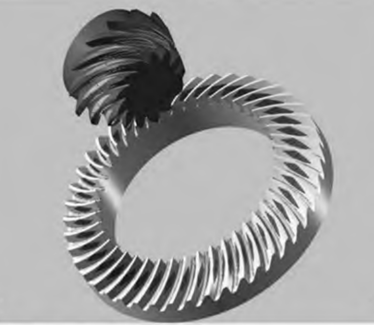
Spiral bevel gears are widely used in aerospace, automotive, and other fields due to their high load-carrying capacity, stable motion, high contact ratio, and controllable contact area. TCA is a crucial technique for evaluating the transmission performance of spiral bevel gears, providing important assessment indicators such as contact pattern and transmission error. However, traditional TCA methods face challenges such as large computational load, low solution efficiency, and poor stability due to strong nonlinearity and numerical coupling relationships.
Table 1. Overview of TCA Development
| Year | Author | Contribution |
|---|---|---|
| 1961 | Baxter [4] | Proposed the concept of TCA and established the first unloaded tooth contact model for hypoid gears. |
| Subsequent Years | Various Researchers [5-20] | Developed and improved TCA algorithms, considering factors such as tooth modifications, manufacturing methods, and installation errors. |
2. Problem Statement
The primary issues with traditional TCA methods for spiral bevel gears include high computational complexity, low solution efficiency, and poor stability. These issues arise due to the complex geometry and nonlinear behavior of spiral bevel gears during meshing.
3. Proposed Method
To address these challenges, this paper proposes a novel TCA collaborative solution method considering both contact pattern and transmission error. The method is outlined below:
3.1. Tooth Surface Parameterization
Based on meshing principles, the tooth surface is parameterized. The rotation matrix is utilized in three-dimensional coordinate space to simulate the meshing motion of the gear pair.
3.2. Contact Path and Transmission Error Calculation
The contact path and transmission error are calculated using the parameterized tooth surfaces and rotation matrix. The interruption condition for meshing points is determined by the transmission error curve intersection, which simplifies the complexity of simultaneously solving equations with ten unknowns.
Table 2. Comparison of Interruption Conditions
| Method | Description | Complexity |
|---|---|---|
| Traditional | Simultaneous solution of equations with ten unknowns | High |
| Proposed | Transmission error curve intersection | Low |
3.3. Contact Pattern Calculation
To calculate the contact pattern, the curvature characteristics of the numerical tooth surface are considered. Instead of solving complex partial derivatives of the meshing equation, rays with uniform angular distribution on the contact tangent plane are used to search for boundary points within the deformation range between the two tooth surfaces, forming an instantaneous contact ellipse.
3.4. Collaborative Solution Algorithm
The proposed method integrates contact pattern and transmission error calculations into a collaborative solution algorithm, ensuring precise and stable TCA evaluations.
4. Case Study
A case study is conducted to validate the feasibility of the proposed method. The gear parameters are summarized in Table 3.
Table 3. Gear Dimensions
| Parameter | Pinion | Gear |
|---|---|---|
| Number of Teeth | 31 | 38 |
| Cone Angle (°) | 23.1667 | 28.8333 |
| Face Cone Angle (°) | 24.2667 | 29.6 |
| Root Cone Angle (°) | 22.4 | 27.7333 |
| Tooth Tip Height (mm) | 5.09 | 3.44 |
| Tooth Root Height (mm) | 4.65 | 6.30 |
| Tooth Width (mm) | 32 | 32 |
| Outer Cone Distance (mm) | 208.81 | 208.81 |
4.1. Results
The contact trajectory and transmission error curve for the entire working tooth surface are calculated.
Note: The image link is a placeholder. Replace it with an actual image URL.
The transmission error amplitude is 108.6 μrad. The contact pattern is calculated by setting the distance between surfaces to d = 0.003 mm.
Note: The image link is a placeholder. Replace it with an actual image URL.
4.2. Comparison with CAGE Software
The TCA results obtained using the proposed method are compared with those from CAGE software. The contact pattern positions and trends are consistent, and the transmission error amplitude is 110.3 μrad, verifying the accuracy of the proposed method.
5. Conclusion
This paper proposes a novel TCA collaborative solution method for spiral bevel gears, considering both contact pattern and transmission error. The method simplifies the calculation process, enhances solution efficiency, and improves stability. The feasibility and accuracy of the proposed method are validated through a case study, demonstrating its potential for practical applications in spiral bevel gear design and analysis.
