
In the realm of mechanical power transmission, spiral bevel gears stand as pivotal components for efficiently transferring motion and torque between intersecting shafts, particularly in demanding applications such as automotive differentials, aerospace systems, petrochemical machinery, and heavy industrial equipment. The unique geometry of spiral bevel gears, characterized by curved teeth that engage gradually, confers significant advantages including high load capacity, smooth and quiet operation, and enhanced durability. My exploration into the manufacturing of these gears reveals that the advent of Numerical Control (NC) machining has revolutionized their production, enabling unprecedented precision, flexibility, and efficiency. This article delves deeply into the principles, processes, and practical implementations of NC machining for spiral bevel gears, employing analytical formulas, comparative tables, and detailed technical discourse to elucidate this complex field. The term ‘spiral bevel gears’ will be frequently reiterated to emphasize the core subject, as these components are fundamental to modern mechanical systems.
The historical development of gear manufacturing, especially for spiral bevel gears, transitioned from mechanical generating methods using dedicated machines like those from Gleason to sophisticated computer-controlled processes. Initially, the generation of spiral bevel gears relied on the principle of conjugate action, where the tooth profile is produced as an envelope of a family of tool surfaces. However, traditional methods often struggled with pre-control of second-order contact parameters, leading to potential inefficiencies and inaccuracies. The breakthrough came with the integration of NC technology, which allows for the independent control of machine tool axes, facilitating the direct machining of complex tooth surfaces through defined tool paths. This paradigm shift, often termed “free-form” or “direct CNC machining,” decouples the process from the constraints of physical master gears or complex mechanical linkages, offering a path to optimize tooth contact patterns and transmission error dynamically.
At the heart of NC machining for spiral bevel gears lies a rigorous mathematical foundation based on gear geometry, kinematics, and differential geometry. The tooth surface of a spiral bevel gear is a complex 3D surface, typically a segment of a spherical involute or a modified geometry defined by machine settings. To machine this surface, one must first establish its mathematical model. Let us consider the position vector of a point on the gear tooth surface in a coordinate system attached to the gear, denoted as \(\mathbf{r}_g(u, \theta)\), where \(u\) and \(\theta\) are surface parameters. The relationship between the gear and the cutting tool (e.g., a milling cutter or grinding wheel) is governed by the condition of continuous tangency or envelope generation. The fundamental equation of meshing between the tool surface \(\mathbf{r}_t(v, \psi)\) and the generated gear surface is given by:
$$ \mathbf{n}_t \cdot \mathbf{v}^{(tg)} = 0 $$
Here, \(\mathbf{n}_t\) is the unit normal vector to the tool surface, and \(\mathbf{v}^{(tg)}\) is the relative velocity vector between the tool and the gear at the contact point. This scalar equation signifies that the relative motion must occur in the tangent plane, ensuring the tool sweeps out the desired gear surface. For spiral bevel gears, the relative motion is multi-axis, involving rotations and translations that simulate the hypoid or bevel gear generation motion. The local synthesis method, a significant advancement, allows for pre-control of contact conditions at a designated reference point \(M\). By specifying parameters such as the gear ratio, shaft angle, and desired second-order characteristics (curvatures), one can solve for the required machine-tool settings. The principal curvatures \(\kappa_1\) and \(\kappa_2\) and their directions at point M on the pinion surface must satisfy a compatibility condition with those on the gear surface to achieve a favorable contact ellipse. This can be expressed through the relative curvature formula:
$$ \kappa_{\text{rel}} = \kappa_{g} – \kappa_{p} $$
where \(\kappa_{g}\) and \(\kappa_{p}\) are the normal curvatures of the gear and pinion along a common direction. Controlling \(\kappa_{\text{rel}}\) governs the size and orientation of the contact ellipse, crucial for load distribution and noise minimization. The table below summarizes key parameters involved in the local synthesis for spiral bevel gears, highlighting their influence on tooth contact performance.
| Parameter | Symbol | Description | Typical Influence on Spiral Bevel Gears |
|---|---|---|---|
| Machine Root Angle | \(\Sigma\) | Angle between tool and workpiece axes | Affects tooth depth and profile curvature |
| Cutter Radius | \(R_c\) | Radius of the cutting tool (blade circle) | Determines tooth lengthwise curvature |
| Velocity Ratio | \(i\) | Relative speed between tool and gear | Defines the spiral angle of the teeth |
| Pressure Angle | \(\alpha\) | Angle between tooth profile and radial line | Impacts load capacity and bending strength |
| Spiral Angle | \(\beta\) | Angle of tooth curvature relative to axis | Governs smoothness of engagement and overlap ratio |
| Contact Ellipse Semi-Axes | \(a, b\) | Dimensions of the theoretical contact patch | Directly related to contact stress and wear |
The NC machining process for spiral bevel gears typically involves several sequential operations: blank preparation, rough cutting, semi-finishing, finishing, and often heat treatment followed by hard finishing (grinding or hard skiving). For the critical tooth cutting phase, two primary strategies exist: the face-milling method and the face-hobbing method. Both can be implemented on multi-axis CNC centers. In the face-milling approach, used for traditional Gleason-style spiral bevel gears, a multi-blade cutter with a circular profile machines one tooth slot at a time in an intermittent indexing process. The cutter axis is tilted relative to the gear axis to generate the spiral. The tool path for each tooth flank is calculated by simulating the relative motion between a virtual crown gear (the generating gear) and the workpiece. The coordinate transformation from the machine settings to the CNC axes (e.g., X, Y, Z, A, B, C) is vital. For a 5-axis CNC machine, the relationship can be encapsulated in a homogeneous transformation matrix \(T\):
$$ T = T_{\text{trans}}(X, Y, Z) \cdot R_{\text{rot}}(A, B, C) $$
where the translational and rotational components are derived from the machine setting parameters like sliding base, swivel angle, and tilt. The face-hobbing method, often associated with the Oerlikon or Klingelnberg systems, employs a continuous indexing process where the cutter and workpiece rotate in a synchronized ratio, producing a tooth flank that is part of an extended epicycloid. This method offers higher productivity and is suitable for large-volume production of spiral bevel gears. The mathematical model for face-hobbing involves more complex kinematics due to the continuous rotation. The basic generation equation can be expressed as:
$$ \mathbf{r}_w(\phi_w) = M_{wg}(\phi_g) \cdot \mathbf{r}_c(\phi_c) $$
Here, \(\mathbf{r}_w\) is a point on the workpiece, \(\mathbf{r}_c\) is a point on the cutter, \(\phi_w\), \(\phi_g\), and \(\phi_c\) are rotation angles of the workpiece, generating gear, and cutter, respectively, and \(M_{wg}\) is the transformation matrix from the cutter to the workpiece coordinate system, which is a function of the time-varying kinematic chain.
To illustrate the practical steps in a typical CNC machining cycle for spiral bevel gears, the following table outlines a generalized process flow with key considerations and objectives at each stage. This process is fundamental for producing high-quality spiral bevel gears.
| Process Stage | NC Machine Operation | Tooling Used | Key Parameters & Objectives | Challenges for Spiral Bevel Gears |
|---|---|---|---|---|
| Blank Machining | Turning, Facing | CNC Lathe, OD/ID Tools | Achieve precise outer dimensions, bore, and back-face. Ensure runout < 0.02mm. | Material removal efficiency for tough alloys like ASTM 9310. |
| Rough Cutting | Multi-axis Milling | Carbide Insert Face Mill | Remove bulk material quickly. Use trochoidal paths to minimize tool load. Depth of cut ~3-5mm. | Managing cutting forces to avoid distortion in thin-web blanks. |
| Semi-Finishing | Precise Profile Milling | Finishing End Mill or Cutter Head | Leave uniform stock (~0.2mm) for finishing. Improve surface consistency. | Accurate compensation for tool deflection and thermal growth. |
| Finishing (Soft State) | Precision Gear Cutting | Plunge or Continuous Cycle with Coated Carbide Tools | Achieve final tooth geometry, lead, profile, and spiral angle. Surface finish Ra < 1.6 µm. | Real-time adaptation to maintain conjugate action and contact pattern. |
| Heat Treatment | Not an NC Operation | Furnace, Quenching System | Case hardening to 58-62 HRC. Control distortion. | Predicting and compensating for post-heat treat distortion in spiral bevel gears. |
| Hard Finishing | CNC Gear Grinding or Hard Skiving | Vitrified Bond CBN Wheel or Skiving Tool | Correct distortion, achieve final micro-geometry and super-fine finish (Ra < 0.4 µm). | Minimizing grinding burns and residual stresses on the hard, curved surfaces. |
| Inspection & Validation | CMM, Gear Analyzer | Touch Probe, Optical Sensors | Verify tooth topography, contact pattern via roll test, and transmission error. | Aligning measurement data with the digital twin of the spiral bevel gear design. |
The application of NC machining for spiral bevel gears extends across industries where reliability under high stress is non-negotiable. In aerospace, for instance, spiral bevel gears are used in helicopter main transmissions and aircraft engine accessory drives. The ability of CNC processes to machine lightweight yet strong materials like titanium alloys or high-strength steels with exacting tolerances is critical. In the energy sector, spiral bevel gears drive pumps and compressors in petrochemical plants, where continuous operation demands exceptional wear resistance. The automotive industry, particularly in high-performance and electric vehicles, relies on precisely manufactured spiral bevel gears in differentials to manage torque vectoring and improve efficiency. The flexibility of CNC programming allows for rapid prototyping and customization of spiral bevel gears for these diverse applications, enabling design iterations that optimize performance metrics such as efficiency, noise-vibration-harshness (NVH), and power density.
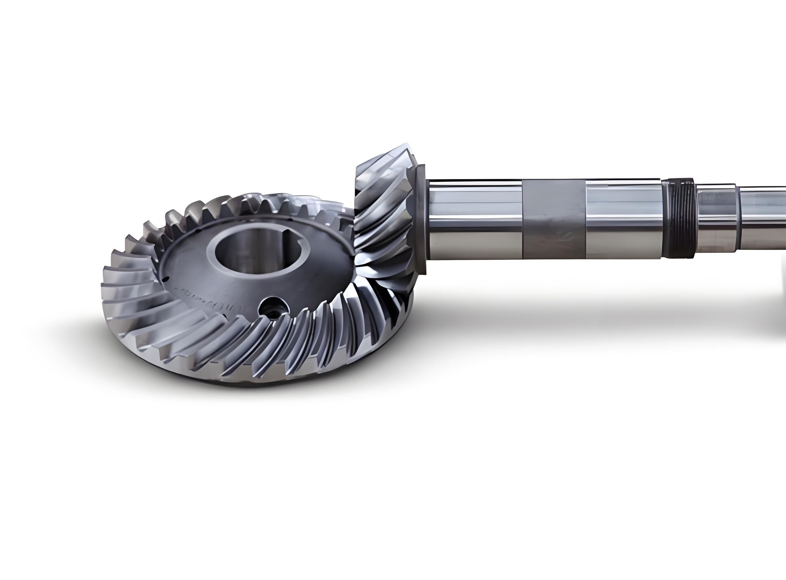
One of the most significant advancements in the NC machining of spiral bevel gears is the integration of simulation and virtual machining environments. Before physical cutting, the entire process is simulated using specialized software that models the cutting mechanics, predicts forces, temperatures, and potential errors like tool deflection or collision. This digital twin approach enables the optimization of tool paths to minimize machining time while ensuring quality. For example, the cutting force \(F_c\) can be estimated using mechanistic models that relate it to the uncut chip thickness \(h\) and specific cutting pressure \(K_c\):
$$ F_c = K_c \cdot b \cdot h $$
where \(b\) is the width of cut. By simulating these forces along the complex tool path for a spiral bevel gear tooth, one can adjust feed rates dynamically to maintain consistent load on the cutter, prolonging tool life and improving surface finish. Furthermore, thermal deformation during dry or high-speed machining of spiral bevel gears can be modeled using finite element analysis (FEA). The temperature rise \(\Delta T\) in the workpiece and tool due to cutting heat generation \(Q\) is governed by the heat conduction equation:
$$ \rho c_p \frac{\partial T}{\partial t} = \nabla \cdot (k \nabla T) + \dot{q} $$
where \(\rho\) is density, \(c_p\) is specific heat, \(k\) is thermal conductivity, and \(\dot{q}\) is the heat generation rate per unit volume. Compensating for this thermal expansion in the CNC program is crucial for maintaining the dimensional accuracy of spiral bevel gears, especially in large-diameter components.
Another critical aspect is the tool path generation strategy. For 5-axis machining of spiral bevel gears, common strategies include flank milling and point milling. In flank milling, the side of the tool is used to sweep the tooth flank, which is efficient but requires precise control of tool orientation to avoid gouging. The tool axis orientation vector \(\mathbf{O}(t)\) as a function of path parameter \(t\) must be calculated to maintain tangency with the design surface along a ruling line. For point milling, the tool tip follows a dense cloud of points on the target surface, offering high accuracy but longer machining times. The choice depends on the required accuracy, batch size, and available machine dynamics. The table below compares these two primary tool path strategies for machining spiral bevel gears on a 5-axis CNC center.
| Aspect | Flank Milling | Point Milling (Sculpturing) |
|---|---|---|
| Machining Principle | Tool side contacts and sweeps along a surface ruling. | Tool tip (ball-nose or flat-end) moves point-by-point on surface. |
| Material Removal Rate | High, suitable for roughing and semi-finishing of spiral bevel gears. | Lower, primarily used for finishing complex free-form shapes. |
| Surface Quality | Can produce scallop marks; depends on tool geometry and path. | Can achieve excellent finish with small step-overs. |
| Computational Complexity | High, requires solving for non-gouging tool orientations. | High, due to large number of CL (cutter location) points. |
| Applicability to Spiral Bevel Gears | Excellent for machining the long, ruled surfaces often found in tooth flanks. | Versatile, can machine any arbitrary tooth modification or repair. |
| Tool Wear | Distributed along tool edge, potentially longer tool life. | Concentrated at tool tip, may require frequent tool changes. |
The future trajectory of NC machining for spiral bevel gears is intertwined with Industry 4.0 concepts, such as adaptive machining, artificial intelligence (AI), and in-process metrology. Adaptive control systems can monitor cutting forces, vibration, and acoustic emissions in real-time, adjusting feed rates and spindle speeds to counteract variations in material hardness or tool wear—common challenges in producing consistent spiral bevel gears. AI algorithms can analyze historical machining data to predict optimal parameters for new gear designs, reducing trial-and-error. Furthermore, the integration of on-machine probing allows for closed-loop manufacturing: the gear is measured immediately after cutting, and any deviations from the nominal geometry are fed back to the CNC controller to modify subsequent tool paths or correct for systematic errors. This is particularly valuable for high-value spiral bevel gears used in mission-critical applications.
In conclusion, the NC machining of spiral bevel gears represents a sophisticated synergy of mechanical engineering, mathematics, and computer science. From the foundational equations of gear geometry to the practical implementation on multi-axis CNC machine tools, every step is aimed at achieving the perfect balance of strength, efficiency, and quiet operation. The parametric design and direct CNC machining approach have liberated the manufacturing of spiral bevel gears from the limitations of dedicated hardware, enabling greater design freedom and faster innovation cycles. As digital technologies continue to evolve, we can anticipate even more intelligent, efficient, and precise manufacturing processes for these indispensable mechanical components, solidifying their role in powering the advanced machinery of tomorrow. The relentless pursuit of perfection in manufacturing spiral bevel gears through NC technology is not just an engineering endeavor but a cornerstone of modern industrial progress.