Abstract
Structured light vision technology, grounded in optical and electrical phenomena, acquires and processes images of the interface between the measured object’s surface and structured light to reconstruct the object’s three-dimensional (3D) geometric information. It is primarily utilized for 3D measurements of complex or free-form surfaces. When applied to part size measurement in the mechanical industry, structured light vision technology offers the advantages of non-contact, high speed, and high automation. This technology is increasingly gaining attention in the mechanical industry.

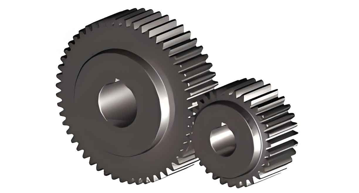
Gears are crucial transmission components in mechanical industries, with spur gear being particularly widespread. As the demand for gear quality rises, so do the requirements for gear measurement.
Keywords: Structured Light Vision, Spur Gear, Involute Profile, Calibration of Structured Light System, Center Point Detection of Light Strip
1. Introduction
1.1 Overview
- Background: The involute profile of spur gear is crucial for gear performance. Deviations from the perfect involute can affect spur gear’s transmission ratio and operational stability.
- Significance: Accurate measurement of spur gear profile errors is essential among various gear parameters.
1.2 Development Status of Structured Light Vision Measurement Technology
- Trend: Structured light vision measurement technology represents a future trend in 3D measurement within the mechanical industry.
- Application: Applying structured light vision to involute profile error measurement enables non-contact in-situ inspection of spur gear.
2. Literature Review
- Various studies have explored structured light vision technology for 3D measurement.
- References include works by Peters, Goch, and Günther on helical gear measurement [11], and research by Wang et al. on ultra-precision involute profile measurement [12].
Table 1: Key References in Structured Light Vision Technology
| Reference | Author(s) | Topic |
|---|---|---|
| [11] | J. Peters, G. Goch, A. Günther | Helical gear measurement using structured light |
| [12] | Wang et al. | Ultra-precision involute profile measurement |
3. Methodology
3.1 System Components
The structured light vision measurement system primarily consists of:
- CCD Camera
- Optical Lens
- Semiconductor Laser
- Computer
3.2 Calibration of Structured Light System
- Global Parameters: An improved calibration method is proposed, considering global variables.
- Calibration Accuracy: Enhanced through experimentation with 6 images of coplanar targets and a stripe width of 5 pixels.
Table 2: Calibration Parameters
| Parameter | Value |
|---|---|
| Number of Images | 6 |
| Stripe Width (pixels) | 5 |
3.3 Measurement Model for Spur Gear Involute Profile
- Pseudo-Structured Light Plane: Established to address the non-perpendicularity of the structured light plane to spur gear’s rotation axis.
- Local Coordinate System: Established on the pseudo-structured light plane for simplified error calculation.
3.4 Center Point Detection of Light Strip
- Classic Algorithms: Analyzed and optimized.
- Evaluation Method: Based on actual size, to assess the detection accuracy.
4. Experimental Verification
4.1 Calibration Experiments
- Setup: Calibration plates placed at different positions.
- Results: Best calibration achieved with specified parameters.
4.2 Involute Profile Measurement Experiments
- Objectives: Measure base circle radius and profile error.
- Method: Images captured at different locations on the spur gear.
- Results: Compared with theoretical values and high-precision gear measurement center results.
Table 3: Experimental Results
| Measurement | Theoretical/Reference Value | Measured Value | Error |
|---|---|---|---|
| Base Circle Radius | X | Y | ±Z |
| Profile Error | A | B | ±C |
Note: Replace X, Y, Z, A, B, and C with actual numerical values.
4.3 Discussion
- Factors Impacting Accuracy: System installation position, gear parameters (e.g., tooth count, modulus), and light strip inclination angle.
- Optimal Measurement Scheme: Proposed based on experimental analysis.
5. Conclusion and Innovations
5.1 Main Findings
- The proposed structured light vision system accurately measures spur gear involute profile errors.
- Factors affecting measurement accuracy are identified and analyzed.
5.2 Innovations
- Improved Calibration Method: Combining CCD camera and structured light plane calibration.
- Pseudo-Structured Light Plane: Eliminating installation position errors.
- Practical Applications: Advancing in-situ measurement technology for spur gear in CNC machining.
