
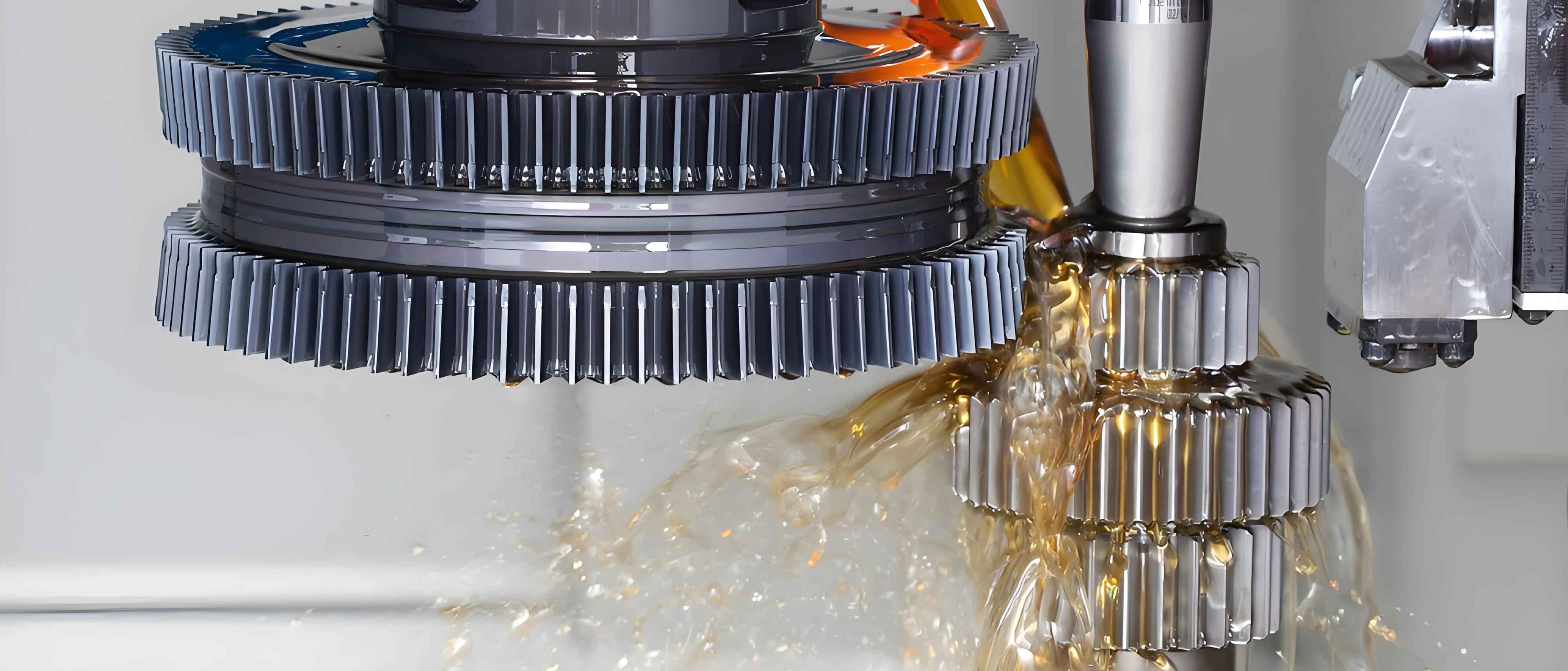
Gear shaping is a widely used method for manufacturing gears, particularly for internal and external gears as well as multi-stage gears. The accuracy of a gear shaping machine directly influences critical gear quality metrics such as pitch error, tooth profile error, and cumulative pitch deviation. Among various factors, the static stiffness at the machine’s end-effector—between the workpiece and the cutter—plays a pivotal role in determining both static and dynamic characteristics, ultimately affecting machining precision. Traditional design approaches in gear shaping machine development often rely on bottom-up methods, which depend heavily on empirical experience and analogical design. These methods involve iterative structural modifications based on finite element analysis (FEA) simulations, leading to complex, parameter-intensive processes that struggle to meet modern performance-driven design demands. In contrast, top-down or forward design methodologies emphasize the intrinsic relationship between the machine’s end-performance and its constituent components, offering a systematic framework to address these limitations. This work focuses on the forward design of static stiffness for CNC gear shaping machines, presenting an analytical modeling approach that establishes a mapping between overall stiffness indices and component-level stiffness attributes. The model is validated through finite element analysis, demonstrating its efficacy as a foundational tool for early-stage design evaluation.
The core objective of this research is to develop a comprehensive static stiffness model for CNC gear shaping machines from a top-down perspective. Static stiffness, defined as the resistance to deformation under applied cutting forces, is crucial for maintaining positional accuracy between the tool and workpiece during gear shaping operations. In gear shaping, the cutting process involves intermittent engagement of the cutter with the workpiece, generating dynamic forces that can induce vibrations and deflections. Therefore, a robust stiffness model must account for the deformations of all structural and functional components along the force transmission path. The proposed methodology begins by defining stiffness characteristics for individual components, analyzing their deformation behaviors under cutting forces, and integrating these into an overall machine model based on the topological structure. This approach not only facilitates rapid stiffness assessment during preliminary design but also enables targeted optimization of critical components to meet desired performance specifications.
To establish the static stiffness model, the first step involves creating a three-dimensional representation of the CNC gear shaping machine and associating coordinate systems with each major component. The machine typically comprises a front bed, Z-axis motion unit, Y-axis motion unit, spindle head, spindle, rotary table, and workpiece. Coordinate systems CS0 through CS7 are fixed to the front bed, rotary table, workpiece, rear bed, column, moving frame, spindle head, and spindle, respectively, with all origins lying in a common plane for simplification. This systematic coordinate assignment allows for precise description of relative positions and deformations. The topological structure of the gear shaping machine dictates how cutting forces propagate from the tool-workpiece interface through various components, each contributing to the overall compliance. By modeling each component’s stiffness as a set of coefficients defined at connection points (e.g., guide rails, ball screws), the deformation behavior can be analytically derived. For instance, the bed’s stiffness coefficients are defined at four slider centers along the X and Y directions, denoted as \(k_{b1x}, k_{b2x}, k_{b3x}, k_{b4x}\) for X-direction and \(k_{b1y}, k_{b2y}, k_{b3y}, k_{b4y}\) for Y-direction. Similarly, the column’s stiffness coefficients include \(k_{c1x}, k_{c1z}, k_{c2x}, k_{c2z}, k_{c3x}, k_{c3z}, k_{c4x}, k_{c4z}\) at slider locations, with additional terms for guideway tangential and normal stiffnesses (\(k_{ygt}, k_{ygn}\)) and ball screw stiffness (\(k_{bsy}\)). Functional components like the rotary table, moving frame, spindle head, and spindle are characterized by directional stiffness coefficients (e.g., \(k_{rx}, k_{ry}, k_{rz}\) for the rotary table). These coefficients serve as fundamental inputs for the deformation analysis.
The deformation of each component under cutting forces is analyzed by considering both translational and rotational displacements. When a unit force is applied at the tool tip in the X, Y, or Z direction, it induces forces and moments on interconnected components. For example, an X-direction force \(F_x\) on the column results in equivalent loads: a force \(F_x\) along X, a moment \(M_{cy} = F_x C_z\) about the Y-axis, and a moment \(M_{cz} = F_x C_y\) about the Z-axis. The translational deformation \(\epsilon_{x34}\) and rotational deformations \(\Delta \beta_{34}\), \(\Delta \gamma_{34}\) are derived based on stiffness coefficients and geometric parameters. However, actual components exhibit coupled deformations due to their continuous nature; for instance, applying force to one slider on a guideway affects adjacent sliders. To address this, correction factors are introduced. Let \(t_c\) and \(n_c\) represent tangential and normal correction factors for the column, respectively. The corrected deformations become:
$$\epsilon’_{x34} = \frac{1}{4} \left( \frac{F_x}{k_{c1x}} + \frac{F_x}{k_{ygt}} \right) \left(1 + \frac{1}{t_c}\right)$$
$$\Delta \beta’_{34} = \frac{F_x C_z}{D_c^2} \left( \frac{1}{k_{c1z}} + \frac{1}{k_{ygn}} \right) \left(1 + \frac{1}{n_c}\right)$$
$$\Delta \gamma’_{34} = \frac{F_x C_y}{L_c^2} \left( \frac{1}{k_{c1x}} + \frac{1}{k_{ygt}} \right) \left(1 + \frac{1}{t_c}\right)$$
Similar analyses are conducted for other components under different force directions. The bed’s deformations include terms like \(\epsilon_{x03}\), \(\Delta \beta_{03}\), and \(\Delta \gamma_{03}\), with correction factors \(t_b\) and \(n_b\). The moving frame’s stiffness is modeled via coefficients \(k_{fx}, k_{fy}, k_{fz}\), leading to deformations such as \(\epsilon_{x45} = F_x / k_{fx}\) and \(\Delta \gamma_{45} = F_x R_f / (f_y^2 k_{fx})\). The spindle head and spindle contribute deformations \(\epsilon_{x56}, \epsilon_{y56}, \epsilon_{z56}\) and \(\epsilon_{x67}, \epsilon_{y67}, \epsilon_{z67}\), respectively. The rotary table, aside from translational stiffness, incorporates torsional stiffness \(k_r\) to account for moments induced by offset forces, yielding \(\Delta \beta_{12} = F_x R_z / k_r\). These component-level deformations are then aggregated to compute the overall tool-workpiece relative displacement.
The relative deformation between the tool and workpiece is derived using homogeneous transformation matrices. Let the ideal transformation matrix from the spindle coordinate system (CS7) to the workpiece coordinate system (CS2) be \(T_{27}\), and the actual matrix under deformation be \(T’_{27}\). The tool tip position in the workpiece coordinates is given by \([x_w, y_w, z_w, 1]^T = T_{27} [x_t, y_t, z_t, 1]^T\) ideally, and \([x’_w, y’_w, z’_w, 1]^T = T’_{27} [x_t, y_t, z_t, 1]^T\) under deformation. Assuming the tool tip at the origin of CS7 (\([x_t, y_t, z_t, 1]^T = [0,0,0,1]^T\)), the displacement vector \([\epsilon_x, \epsilon_y, \epsilon_z, 1]^T\) is obtained by subtracting the ideal from actual positions. After simplification, neglecting second-order infinitesimals, the overall machine deformation expressions are:
$$\begin{bmatrix} \epsilon_x \\ \epsilon_y \\ \epsilon_z \end{bmatrix} = \begin{bmatrix} -\epsilon_{x01} – \epsilon_{x12} + \epsilon_{x03} + \epsilon_{x34} + \epsilon_{x45} + \epsilon_{x56} + \epsilon_{x67} – P_z \Delta \beta_{12} – B_y \Delta \gamma_{03} + C_y \Delta \gamma_{34} + R_f \Delta \gamma_{45} + B_z \Delta \beta_{03} + C_z \Delta \beta_{34} \\ -\epsilon_{y01} – \epsilon_{y12} + \epsilon_{y03} + \epsilon_{y34} + \epsilon_{y45} + \epsilon_{y56} + \epsilon_{y67} – B_z \Delta \alpha_{03} – C_z \Delta \alpha_{34} \\ -\epsilon_{z01} – \epsilon_{z12} + \epsilon_{z03} + \epsilon_{z34} + \epsilon_{z45} + \epsilon_{z56} + \epsilon_{z67} + B_y \Delta \alpha_{03} – C_y \Delta \alpha_{34} – R_f \Delta \alpha_{45} \end{bmatrix}$$
where \(P_z = Z_{03} – Z_{12} – Z_{45}\), \(B_y = -Y_{34} + Y_{56} + Y_{67}\), \(C_y = R_f = Y_{56} + Y_{67}\), and \(B_z = C_z = Z_{45}\) are geometric parameters representing distances between components. Substituting the corrected deformation formulas for each component yields the comprehensive static stiffness model. The overall machine stiffness is partitioned into tool-side and workpiece-side contributions for computational convenience. Let \(k_{tx}, k_{ty}, k_{tz}\) denote the tool-side stiffness in X, Y, Z directions, and \(k_{wx}, k_{wy}, k_{wz}\) for the workpiece-side. The total stiffness is given by:
$$\begin{bmatrix} \frac{1}{k_x} \\ \frac{1}{k_y} \\ \frac{1}{k_z} \end{bmatrix} = \begin{bmatrix} \frac{1}{k_{tx}} + \frac{1}{k_{wx}} \\ \frac{1}{k_{ty}} + \frac{1}{k_{wy}} \\ \frac{1}{k_{tz}} + \frac{1}{k_{wz}} \end{bmatrix}$$
The tool-side stiffness model incorporates terms from the moving frame, spindle head, spindle, and column-related deformations. For instance, the X-direction tool-side compliance includes:
$$\frac{1}{k_{tx}} = \frac{1}{k_{fx}} + \frac{1}{k_{hx}} + \frac{1}{k_{sx}} + \frac{1}{k’_{fxx}} + \frac{1}{k’_{cxx1}} + \frac{1}{k’_{ygtx1}} + \frac{1}{k’_{cxx2}} + \frac{1}{k’_{ygtx2}} + \frac{1}{k’_{czx}} + \frac{1}{k’_{ygnx}}$$
where derived stiffness terms like \(k’_{fxx} = \frac{f_y^2 k_{fx}}{R_f^2}\), \(k’_{cxx1} = \frac{4}{1 + 1/t_c} \cdot k_{c1x}\), and \(k’_{ygtx1} = \frac{4}{1 + 1/t_c} \cdot k_{ygt}\) emerge from the deformation analysis. Similarly, the workpiece-side stiffness model involves the rotary table, bed, and associated components. The Y-direction workpiece-side compliance, for example, is expressed as:
$$\frac{1}{k_{wy}} = \frac{1}{k_{ry}} + \frac{1}{k_{py}} + \frac{1}{k’_{byy1}} + \frac{1}{k’_{zgny1}} + \frac{1}{k’_{byy2}} + \frac{1}{k’_{zgny2}}$$
with terms such as \(k’_{byy1} = \frac{4}{1 + 1/n_b} \cdot k_{b1y}\). These analytical expressions establish a direct mapping from component stiffness parameters to the overall machine stiffness, enabling forward design where target stiffness values can be decomposed into component requirements.
To validate the analytical model, a finite element analysis (FEA) is conducted on a specific CNC gear shaping machine model. The machine’s basic dimensions are summarized in Table 1, which are critical for calculating geometric parameters in the stiffness formulas.
| Parameter | Value (mm) | Parameter | Value (mm) |
|---|---|---|---|
| \(R_z\) | 480 | \(B_y\) | 410 |
| \(C_y\) | 450 | \(B_z\) | 470 |
| \(L_x\) | 500 | \(L_c\) | 500 |
| \(L_z\) | 500 | \(D_c\) | 250 |
| \(P_z\) | 180 |
Stiffness coefficients for components are determined through FEA simulations and product catalog data. For example, the column’s X-direction stiffness \(k_{c1x}\) is evaluated by applying a 1000 N force at slider locations and measuring deformation, yielding 1748 N/μm. Similarly, other coefficients are obtained as listed in Table 2.
| Stiffness Coefficient | Value (N/μm) | Stiffness Coefficient | Value (N/μm) |
|---|---|---|---|
| \(k_{sx}\) | 729 | \(k_{b1x}\) | 3301 |
| \(k_{sy}\) | 7010 | \(k_{b1y}\) | 5581 |
| \(k_{sz}\) | 729 | \(k_{c1x}\) | 1748 |
| \(k_{hx}\) | 1082 | \(k_{c1z}\) | 2215 |
| \(k_{hy}\) | 8443 | \(k_{fx}\) | 11305 |
| \(k_{hz}\) | 1076 | \(k_{fy}\) | 29274 |
| \(k_{rx}\) | 180401 | \(k_{fz}\) | 28203 |
| \(k_{ry}\) | 671501 | \(k_{bsy}\) | 310 |
| \(k_{rz}\) | 166444 | \(k_{bsz}\) | 180 |
| \(k_{px}\) | 18183 | \(k_{ygn}\) | 2429 |
| \(k_{py}\) | 68903 | \(k_{ygt}\) | 1395 |
| \(k_{pz}\) | 18183 | \(k_{zgn}\) | 1875 |
| \(k_{zgt}\) | 1286 |
Correction factors are derived by comparing deformations under single and multiple slider loadings in FEA. For the column, applying a normal force to one slider yields a deformation of 0.19436 μm, while two sliders result in 0.21589 μm, giving \(1/n_c = (0.21589 – 0.19436) / 0.19436 = 0.111\). Similarly, tangential correction factors are computed. Table 3 summarizes these factors.
| Correction Factor | \(1/t_c\) | \(1/n_c\) | \(1/t_b\) | \(1/n_b\) |
|---|---|---|---|---|
| Value | 0.452 | 0.111 | -0.303 | 1.384 |
Using these inputs, the analytical model computes overall stiffness values. For validation, a full-machine FEA model is constructed in ANSYS Workbench. The model simplifies components while retaining key features; guideways and ball screws are represented via spring elements. Fixed constraints are applied at the bed base. Cutting forces of 1000 N, 1500 N, and 2000 N are applied at the tool tip in X, Y, and Z directions, with equal and opposite forces on the workpiece. Deformation results for the 1500 N case show tool-tip displacements, from which stiffness values are derived. For example, X-direction stiffness \(k_x = 1500 / (12.369 – (-0.058512)) = 120.7\) N/μm. Similar calculations yield \(k_y = 165.6\) N/μm and \(k_z = 117.8\) N/μm. The FEA results across different force magnitudes show consistent stiffness values, indicating linear behavior within this range. A comparison with analytical predictions is presented in Table 4.
| Stiffness | Analytical Model (N/μm) | FEA (1000 N) | FEA (1500 N) | FEA (2000 N) | Difference |
|---|---|---|---|---|---|
| \(k_x\) | 106 | 120.2 | 120.7 | 120.33 | 13.8% |
| \(k_y\) | 158 | 165.26 | 165.6 | 165.28 | 4.8% |
| \(k_z\) | 99 | 117.25 | 117.8 | 117.31 | 18.9% |
The discrepancies between analytical and FEA results, up to 18.9% in the Z-direction, are attributed to simplifications in the analytical model. Specifically, the analytical approach treats components as rigid bodies with discrete stiffness at connection points, whereas FEA accounts for distributed flexibility and complex deformation modes such as bending and torsion of entire structures. For instance, the bed and column deform as continuous entities under load, leading to smaller overall deformations than predicted by lumped stiffness models. Nevertheless, the differences are within acceptable limits for early design stages, confirming the model’s utility for rapid stiffness assessment. This validation underscores the effectiveness of the top-down approach in gear shaping machine design, where the analytical model provides a quick estimate while FEA offers refined verification.
The proposed static stiffness model offers several advantages for forward design in gear shaping applications. Firstly, it explicitly links component-level stiffness characteristics to system-level performance, enabling designers to set target stiffness values and derive requirements for individual parts. This is particularly beneficial in optimizing critical components like guideways, ball screws, and structural frames to enhance overall machine rigidity. Secondly, the model accommodates various gear shaping configurations by adjusting geometric parameters and stiffness coefficients. For example, different workpiece sizes or cutter positions can be simulated by modifying terms like \(P_z\) or \(B_y\). Thirdly, the analytical framework supports sensitivity analysis, identifying which components most significantly influence total stiffness. This guides cost-effective design improvements, as strengthening a high-impact component yields greater performance gains than modifying less sensitive ones. Additionally, the model can be extended to dynamic stiffness analysis by incorporating frequency-dependent terms, though that is beyond the current scope. In practice, gear shaping machines often operate under varying cutting conditions; thus, future work could integrate cutting force models to predict stiffness requirements across different gear shaping operations.
In conclusion, this work presents a comprehensive static stiffness modeling methodology for CNC gear shaping machines from a top-down design perspective. By defining stiffness coefficients for components, analyzing their deformations under cutting forces, and integrating these into an overall analytical model, a direct mapping between component attributes and machine stiffness is established. The model is validated through finite element analysis, showing reasonable agreement despite simplifications. This approach facilitates early-stage design evaluation, allowing engineers to quickly assess stiffness performance and optimize components before detailed prototyping. As gear shaping technology advances towards higher precision and efficiency, such forward design tools become increasingly valuable for developing robust, high-performance machines. Future research may focus on incorporating nonlinear effects, thermal deformations, and dynamic interactions to further refine the model, ultimately enhancing the accuracy and reliability of gear shaping processes.